Question-and-Answer Resource for the Building Energy Modeling Community
| | 1 | initial version |
I'll let more knowledgeable people chime in, because I'm a bit confused too.
I think this includes all piping from the outdoor unit to the indoor unit itself. It's used to calculate both the heat loss and pressure drop.
See Engineering Reference, especially "Step 2c.1: Piping loss calculation in the cooling mode"
$$P_s=P_e− \Delta P_{pipe}$$
With $P_s$ the compressor suction, $P_e$ the evaporating pressure, and $\Delta P_{pipe}$ the pressure drop in the pipe.
The associated diagram at the beginning of the Model Description is very interesting too:
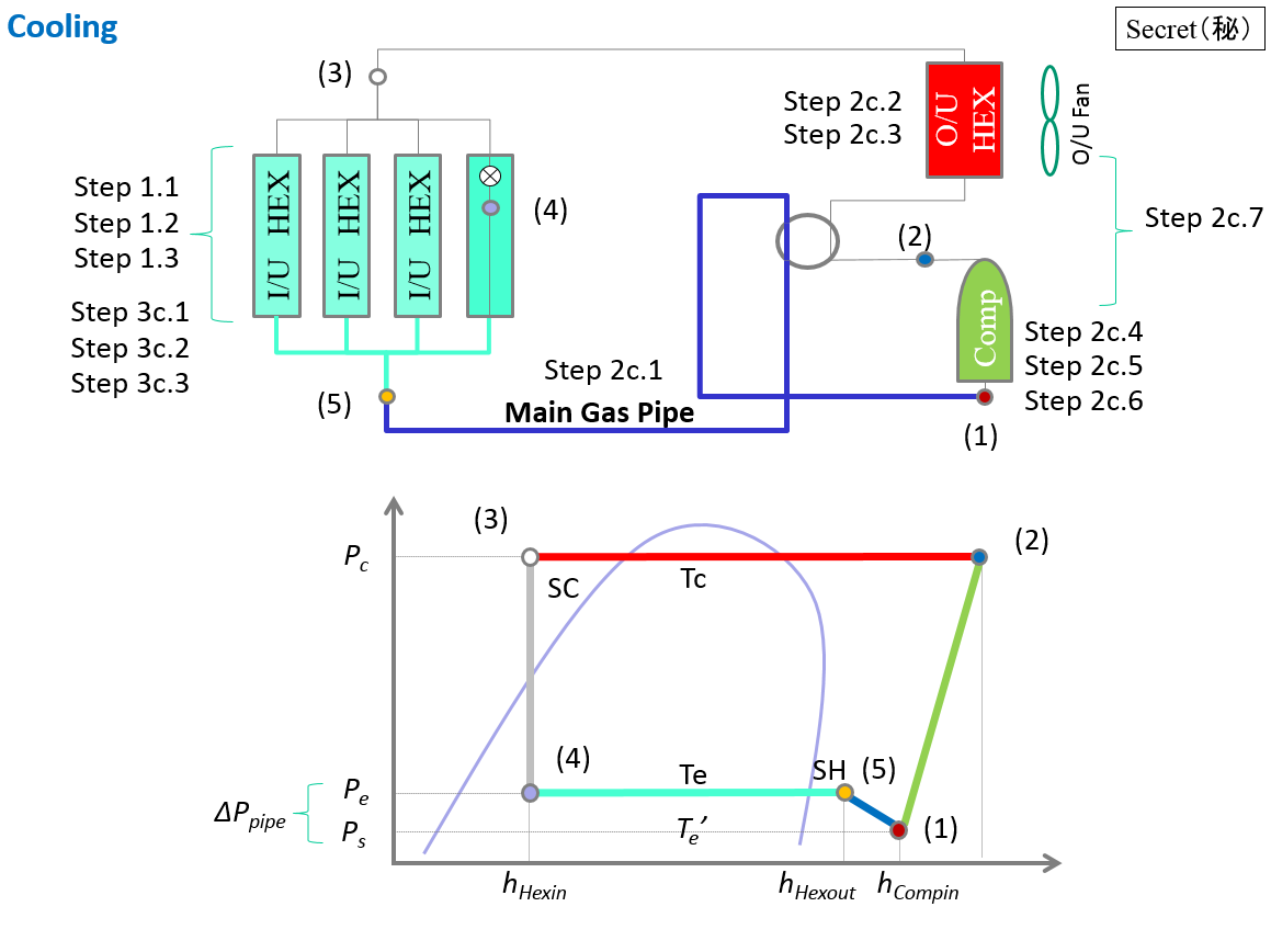
As you can see, the $\Delta P_{pipe}$ is between (1) and (4), so up to the indoor unit. Yet the "Main Gas Pipe" in blue appears to run until (5) only, hence my confusion.
I briefly checked the source code around here, it seems it's up to the evaporator side of the Indoor Unit...
You perhaps want to look at the equivalent piping method if you need to calculate equivalent properties for different diameters. Maybe the piping loss after the branch is negligible?
(Bonus point for any explanation about the "Secret" label on the top right corner of pretty much every image of this chapter)


