 | 1 | initial version |
The OnOffFanPartLoadFraction variable is used to modify PLR for energy calculations as RTF = PLR / PLF. Where PLF = OnOffFanPartLoadFraction = the Part Load Fraction Correlation Curve result from the DX coil or gas heater performance curve. This accounts for the cycling losses of coils where they take a finite amount of time to reach steady state operation (about 30-90 seconds-ish). The longer the coil runs, the less startup losses affect performance.
The code you looked at is used as a check to make sure PLF is not > 1.
If PLF = 1 or no curve is used, then RTF = PLR, otherwise RTF > PLR. RTF should never = 1 when PLR < 1. And PLF should never be less than 0.7. A typical PLR curve would be PLF = 0.8 + 0.2 * PLR. For example, PLF = 0.8002 and PLR = 0.001, then RTF = 0.00125, just slightly higher than PLR. At higher PLRs, PLF is also higher and approaches 1 where RTF = PLR = 1.
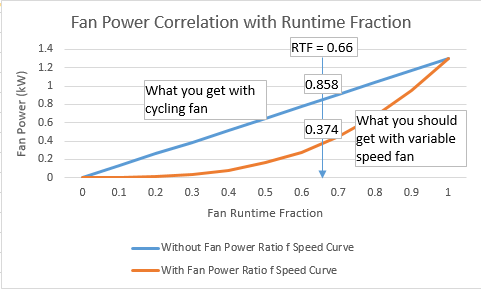
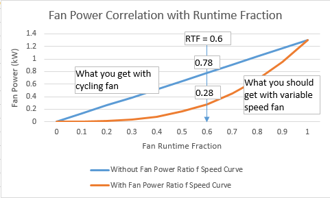
The fan power curve is a function of the cube of the speed, so PLR = 0.6 should result in about a 0.22 multiplier of full load power, which is close to what you are seeing. I think usually it's not a perfect cube and instead somewhat lower like 2.6 or so. Refresh the basics here
 | 2 | No.2 Revision |
The OnOffFanPartLoadFraction variable is used to modify PLR for energy calculations as RTF = PLR / PLF. Where PLF = OnOffFanPartLoadFraction = the Part Load Fraction Correlation Curve result from the DX coil or gas heater performance curve. This accounts for the cycling losses of coils where they take a finite amount of time to reach steady state operation (about 30-90 seconds-ish). The longer the coil runs, the less startup losses affect performance.
The code you looked at is used as a check to make sure PLF is not > 1.
If PLF = 1 or no curve is used, then RTF = PLR, otherwise RTF > PLR. RTF should never = 1 when PLR < 1. And PLF should never be less than 0.7. A typical PLR PLF curve would be PLF = 0.8 + 0.2 * PLR. For example, PLF = 0.8002 and PLR = 0.001, then RTF = 0.00125, just slightly higher than PLR. At higher PLRs, PLF is also higher and approaches 1 where RTF = PLR = 1.
The fan power curve is a function of the cube of the speed, so PLR = 0.6 should result in about a 0.22 multiplier of full load power, which is close to what you are seeing. I think usually it's not a perfect cube and instead somewhat lower like 2.6 or so. Refresh the basics here
 | 3 | No.3 Revision |
The OnOffFanPartLoadFraction variable is used to modify PLR for energy calculations as RTF = PLR / PLF. Where PLF = OnOffFanPartLoadFraction = the Part Load Fraction Correlation Curve result from the DX coil or gas heater performance curve. This accounts for the cycling losses of coils where they take a finite amount of time to reach steady state operation (about 30-90 seconds-ish). The longer the coil runs, the less startup losses affect performance.
The code you looked at is used as a check to make sure PLF is not > 1.
If PLF = 1 or no curve is used, then RTF = PLR, otherwise RTF > PLR. RTF should never = 1 when PLR < 1. And PLF should never be less than 0.7. A typical PLF curve would be PLF = 0.8 + 0.2 * PLR. For example, PLF = 0.8002 and PLR = 0.001, then RTF = 0.00125, just slightly higher than PLR. At higher PLRs, PLF is also higher and approaches 1 where RTF = PLR = 1.
The fan power curve is a function of the cube of the speed, so PLR = 0.6 should result in about a 0.22 multiplier of full load power, which is close to what you are seeing. I think usually it's not a perfect cube and instead somewhat lower higher like 2.6 0.26 or so. Refresh the basics here
Update:
The original intent was to include a speed ratio multiplier to allow VS fans to model power more closely. The model now calculates fan power based on the RTF of the fan (i.e., the ratio of actual air flow to max air flow) and then applies the fan power as a function of speed ratio result. So it appears to be a modifier to the result of the previous fan model (your second curve is correct). I agree this is confusing and will need to discuss this with other team members to determine a solution since just updating the documentation may not be the best course of action.
The new speed curve is used to allow a VS fan to be modeled using the cubed fan law. I guess I was attempting to show you was what the actual fan power should be instead of realizing you wanted to apply your own modifier (i.e., the fan law modifier at PLR=0.6 = 0.216 and you are trying to apply 0.4 as the total modifier (when 0.6*0.4 = 0.24 which is close to what I believe the resulting fan power should be).
P.S. I was using your modified curve on my last response (your idf as you sent it).

 | 4 | No.4 Revision |
The OnOffFanPartLoadFraction variable is used to modify PLR for energy calculations as RTF = PLR / PLF. Where PLF = OnOffFanPartLoadFraction = the Part Load Fraction Correlation Curve result from the DX coil or gas heater performance curve. This accounts for the cycling losses of coils where they take a finite amount of time to reach steady state operation (about 30-90 seconds-ish). The longer the coil runs, the less startup losses affect performance.
The code you looked at is used as a check to make sure PLF is not > 1.
If PLF = 1 or no curve is used, then RTF = PLR, otherwise RTF > PLR. RTF should never = 1 when PLR < 1. And PLF should never be less than 0.7. A typical PLF curve would be PLF = 0.8 + 0.2 * PLR. For example, PLF = 0.8002 and PLR = 0.001, then RTF = 0.00125, just slightly higher than PLR. At higher PLRs, PLF is also higher and approaches 1 where RTF = PLR = 1.
The fan power curve is a function of the cube of the speed, so PLR = 0.6 should result in about a 0.22 multiplier of full load power, which is close to what you are seeing. I think usually it's not a perfect cube and instead somewhat higher like 0.26 or so. Refresh the basics here.
Update:
The original intent was to include a speed ratio multiplier to allow VS fans to model power more closely. The model now calculates fan power based on the RTF of the fan (i.e., the ratio of actual air flow to max air flow) and then applies the fan power as a function of speed ratio result. So it appears to be a modifier to the result of the previous fan model (your second curve is correct). I agree this is confusing and will need to discuss this with other team members to determine a solution since just updating the documentation may not be the best course of action.
The new speed curve is used to allow a VS fan to be modeled using the cubed fan law. I guess I was attempting to show you was what the actual fan power should be instead of realizing you wanted to apply your own modifier (i.e., the fan law modifier at PLR=0.6 = 0.216 and you are trying to apply 0.4 as the total modifier (when 0.6*0.4 = 0.24 which is close to what I believe the resulting fan power should be).
P.S. I was using your modified curve on my last response (your idf as you sent it).


 | 5 | No.5 Revision |
The OnOffFanPartLoadFraction variable is used to modify PLR for energy calculations as RTF = PLR / PLF. Where PLF = OnOffFanPartLoadFraction = the Part Load Fraction Correlation Curve result from the DX coil or gas heater performance curve. This accounts for the cycling losses of coils where they take a finite amount of time to reach steady state operation (about 30-90 seconds-ish). The longer the coil runs, the less startup losses affect performance.
The code you looked at is used as a check to make sure PLF is not > 1.
If PLF = 1 or no curve is used, then RTF = PLR, otherwise RTF > PLR. RTF should never = 1 when PLR < 1. And PLF should never be less than 0.7. A typical PLF curve would be PLF = 0.8 + 0.2 * PLR. For example, PLF = 0.8002 and PLR = 0.001, then RTF = 0.00125, just slightly higher than PLR. At higher PLRs, PLF is also higher and approaches 1 where RTF = PLR = 1.
The fan power curve is a function of the cube of the speed, so PLR = 0.6 should result in about a 0.22 multiplier of full load power, which is close to what you are seeing. I think usually it's not a perfect cube and instead somewhat higher like 0.26 or so. Refresh the basics here.
Update:
The original intent was to include a speed ratio multiplier to allow VS fans to model power more closely. The model now calculates fan power based on the RTF of the fan (i.e., the ratio of actual air flow to max air flow) and then applies the fan power as a function of speed ratio result. So it appears to be a modifier to the result of the previous fan model (your second curve is correct). I agree this is confusing and will need to discuss this with other team members to determine a solution since just updating the documentation may not be the best course of action.
The new speed curve is used to allow a VS fan to be modeled using the cubed fan law. I guess I was attempting to show you was what the actual fan power should be instead of realizing you wanted to apply your own modifier (i.e., the fan law modifier at PLR=0.6 = 0.216 and you are trying to apply 0.4 as the total modifier (when 0.6*0.4 = 0.24 which is close to what I believe the resulting fan power should be).
P.S. I was using your modified curve on my last response (your idf as you sent it).

