Question-and-Answer Resource for the Building Energy Modeling Community
| | 1 | initial version |
So, it seems that with this plant loop:
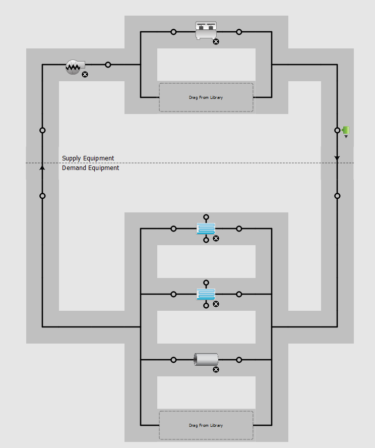 ,
,
I get this pump flow:
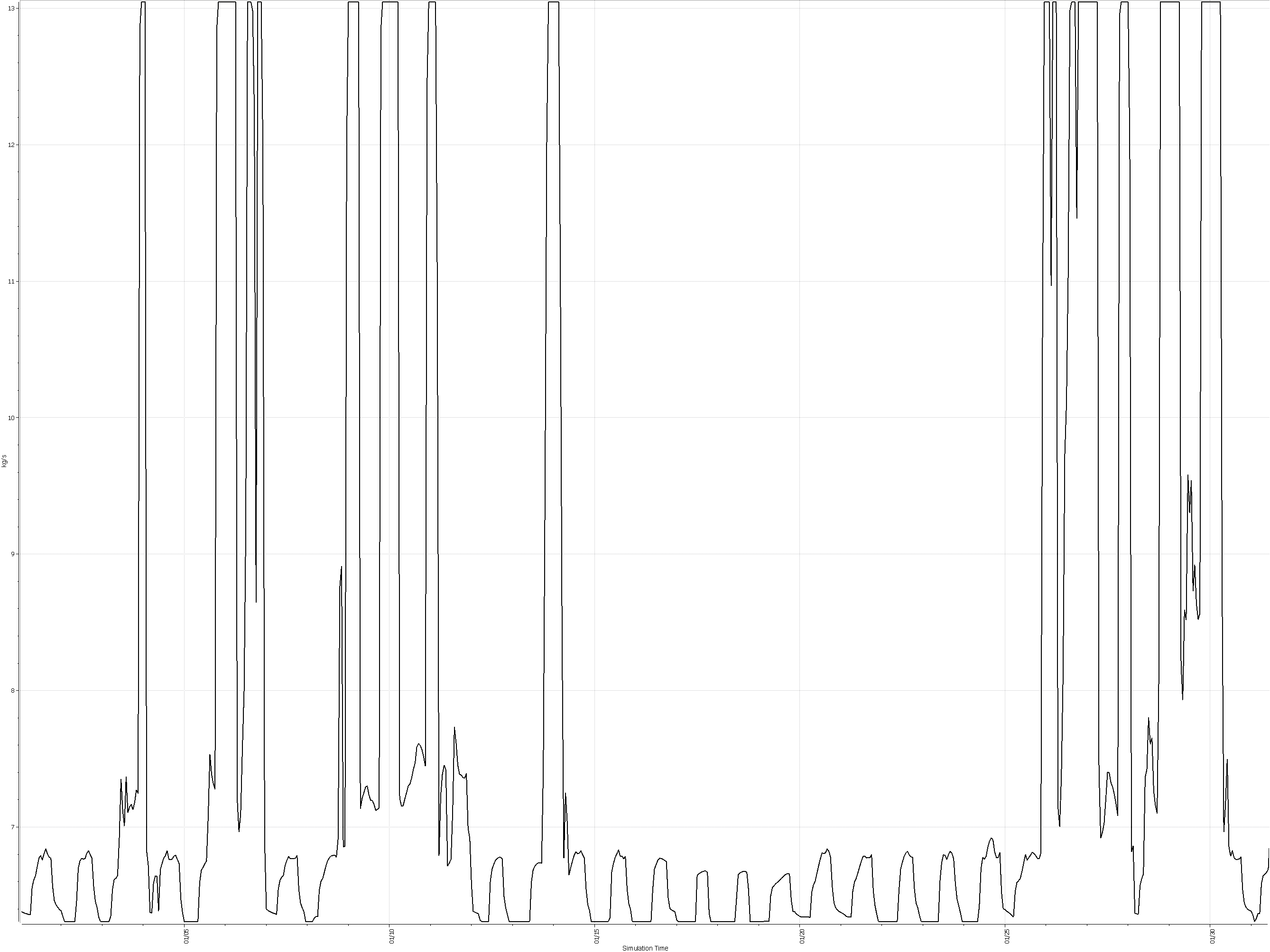 .
.
The low range is about 6.31 kg/s, corresponding to 100 gpm. The high range falls somewhat short of the 13.56 kg/s or 215 gpm that the loop was designed to go to, but I suppose that is so because full flow is not really needed to meet the load. Interestingly, setting the plant loop to 100 gpm minimum was not sufficient, I also had to set the pump to 100 gpm minimum, rather than the 77.2 gpm that is actually could go to. Also, I left the pump at "continuous" rather than "intermittent", as it should have to run even when there are no loads on the coils. I think this is close to what I needed, so thanks again for setting me on the right track! HOWEVER, I do not know how to plot the flow through the bypass or the AHU (there seem to be no variables for that in the .rdd file), so any help with that would still be much appreciated.

