Question-and-Answer Resource for the Building Energy Modeling Community
| | 1 | initial version |
I just did a quick test and I believe this configuration is what you're looking for:
Pipe:Adiabatic on the demand side.Pump:VariableSpeed on the supply side.Chiller:Electric:EIR PlantLoop Pump:VariableSpeed 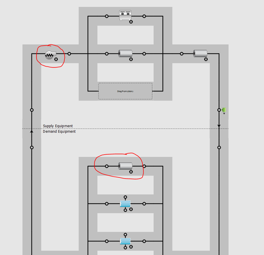
Here's the result (sorry the pictures are so small):
At Point A, the Chiller (black, top) is running and the pump (red, bottom) is pumping above the minimum flow rate but there's no flow through the bypass (orange, bottom).
At Point B, the Chiller (black, top) is running at a lower power. The pump (red, bottom) is pumping at the minimum flow rate even though the coils aren't calling for flow. Whatever the coils don't need flows through the bypass (orange, bottom).
In this plot of CHW pump and CHW bypass vs. Chiller part load, you can see that when the chilled water pump (red) is above the minimum flow (horizontal black line), there is barely ever any flow through the bypass (orange). However, when the chilled water pump is at minimum flow, there is often lots of flow through the bypass, with the bypass flow topping out at the minimum CHW flow rate.
| | 2 | No.2 Revision |
I just did a quick test and I believe this configuration is what you're looking for:
Pipe:Adiabatic on the demand side.Pump:VariableSpeed on the supply side.Chiller:Electric:EIR PlantLoop Pump:VariableSpeed
Here's the result (sorry the pictures are so small):
At Point A, the Chiller (black, top) is running and the pump (red, bottom) is pumping above the minimum flow rate but there's no flow through the bypass (orange, bottom).
At Point B, the Chiller (black, top) is running at a lower power. The pump (red, bottom) is pumping at the minimum flow rate even though the coils aren't calling for flow. Whatever the coils don't need flows through the bypass (orange, bottom).
In this plot of CHW pump and CHW bypass vs. Chiller part load, you can see that when the chilled water pump (red) is above the minimum flow (horizontal black line), there is barely ever any flow through the bypass (orange). However, when the chilled water pump is at minimum flow, there is often lots of flow through the bypass, with the bypass flow topping out at the minimum CHW flow rate.
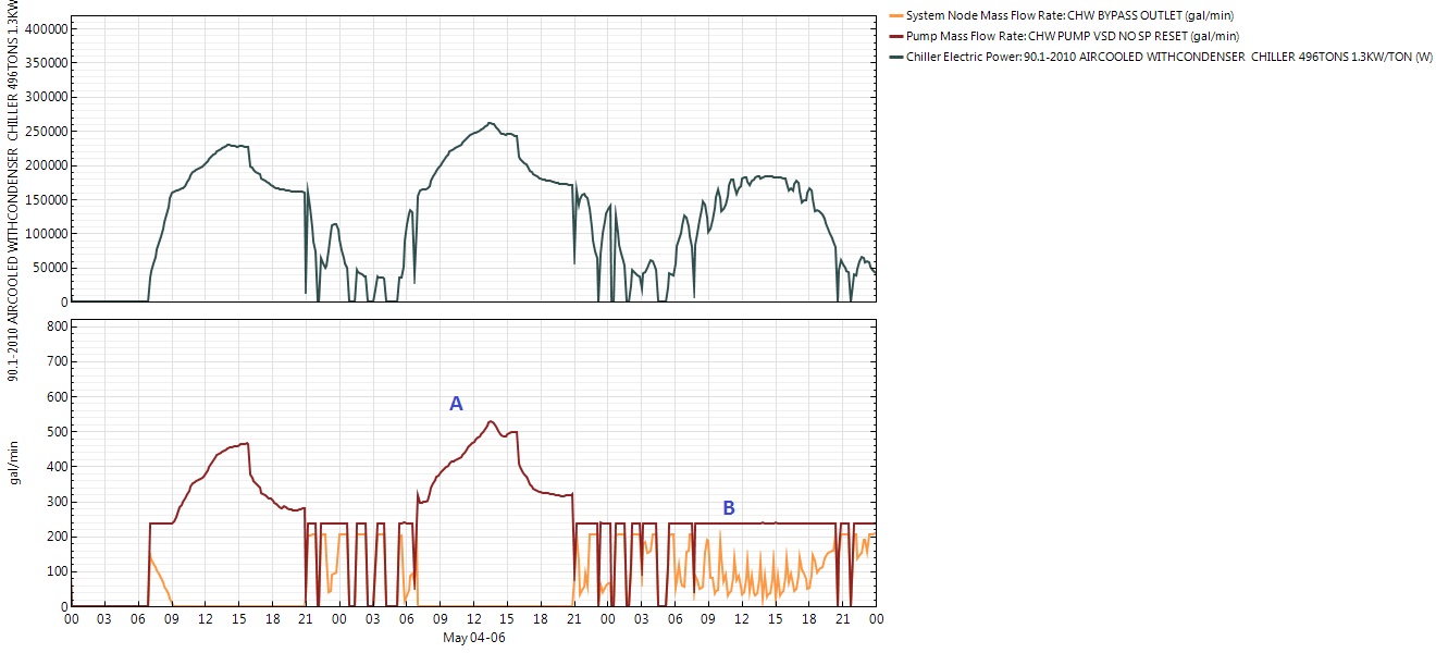
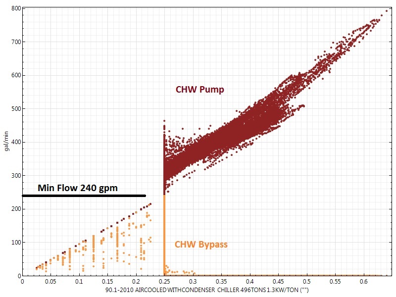
| | 3 | No.3 Revision |
I just did a quick test and I believe this configuration is what you're looking for:
Pipe:Adiabatic on the demand side.Pump:VariableSpeed on the supply side.Chiller:Electric:EIR PlantLoop Pump:VariableSpeed Here's the result (sorry the pictures are so small):
At Point A, the Chiller (black, top) is running and the pump (red, bottom) is pumping above the minimum flow rate but there's no flow through the bypass (orange, bottom).
At Point B, the Chiller (black, top) is running at a lower power. The pump (red, bottom) is pumping at the minimum flow rate even though the coils aren't calling for flow. Whatever the coils don't need flows through the bypass (orange, bottom).
In this plot of CHW pump and CHW bypass vs. Chiller part load, you can see that when the chilled water pump (red) is above the minimum flow (horizontal black line), there is barely ever any flow through the bypass (orange). However, when the chilled water pump is at minimum flow, there is often lots of flow through the bypass, with the bypass flow topping out at the minimum CHW flow rate.


