Question-and-Answer Resource for the Building Energy Modeling Community
First time here? Check out the Help page!
| | 1 | initial version |
You're correct, placing the ERV HX on the supply and exhaust nodes of the outdoor air mixer DOES NOT MATCH the schematic above. To match, the ERV HX should be placed between the return air node and the outdoor air mixer. Reference my annotated image of your schematic, where red boxes represent HVAC components, circles are for important air nodes, and arrows show flow of process air.
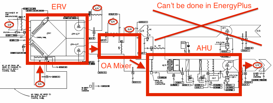
There are two big issues I see with modeling this exact system:
EnergyPlus has a AirLoopHVAC:OutdoorAirSystem object that serves as the sub-system that introduces outdoor air and has a list of equipment that shape the outdoor air system. According to the Engineering Reference for this object:
The OutdoorAir:Mixer should be the first component in the AirLoopHVAC:OutdoorAirSystem:EquipmentList object.
You can try to connect the ERV as a stand-alone component that isn't part of the outdoor air system. Again, the inlet for the ERV process air should be return air and the outlet for the ERV process air should be the same as the inlet for the OA mixer process air.
AirLoopHVAC:ZoneSplitter object before the ERV, and a AirLoopHVAC:ZoneMixer object after the OA mixer. Documentation for both of these objects states they must be on the demand loop (supply path or return path) of air systems, NOT the supply loop. You'll also need to make sure the AirLoopHVAC object references the multiple Branches and Connectors accordingly. Like @Eric Ringold stated above, the "Heat Recovery Bypass Control Type" input field of the OA controller object may be the closest you can get.Good Luck!


