Question-and-Answer Resource for the Building Energy Modeling Community
First time here? Check out the Help page!
| | 1 | initial version |
I ran the VariableRefrigerantFlow_5Zone example file and also changed the condenser type to EvaporitivelyCooled. The results shown in the Component Sizing Summary using V8.4 appear correct. The first table denotes the air-cooled simulation while the second table reflects the results of the evap-cooled simulation. The results show the values for autosized input fields.
| | 2 | No.2 Revision |
I ran the VariableRefrigerantFlow_5Zone example file and also changed the condenser type to EvaporitivelyCooledEvaporativelyCooledautosized input fields.
| | 3 | No.3 Revision |
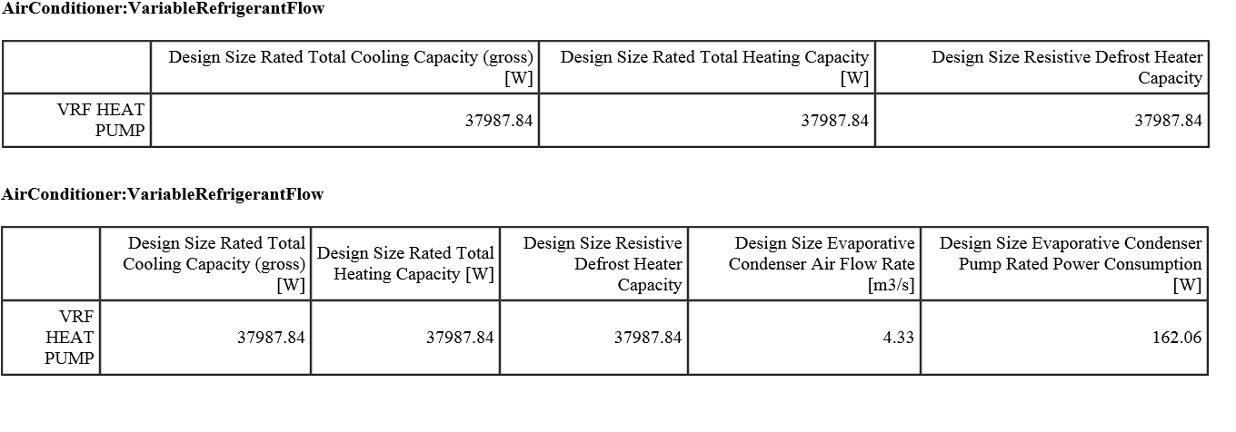
I ran the VariableRefrigerantFlow_5Zone example file and also changed the condenser type to EvaporativelyCooled. The results shown in the Component Sizing Summary using V8.4 appear correct. The first table denotes the air-cooled simulation while the second table reflects the results of the evap-cooled simulation. The results show the values for autosized input fields.
| | 4 | No.4 Revision |
I ran the VariableRefrigerantFlow_5Zone example file and also changed the condenser type to EvaporativelyCooled. The results shown in the Component Sizing Summary using V8.4 appear correct.
The first table denotes the air-cooled air-cooled simulation while the second table reflects the results of the evap-cooled evap-cooled simulation. The results show the values for autosized input fields.