Question-and-Answer Resource for the Building Energy Modeling Community
First time here? Check out the Help page!
| 2016-04-27 21:40:39 -0500 | asked a question | Cooling Coil Controller Error When Using Temperature Reset for Chilled Water Setpoint I've been trying to tighten up my baseline model before submitting to LEED, and wanted to dig into a severe error that might raise some flags. The model is of a large k-12 school, and I'm using the Now the weird thing is, by comparing my file to the So my questions are:
Thanks for any help! |
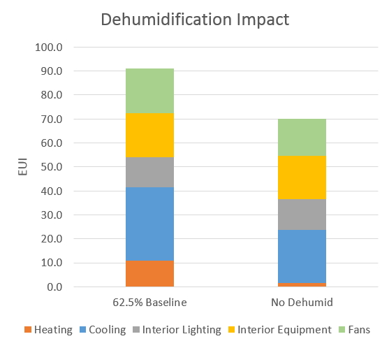
| 2015-03-10 14:51:20 -0500 | asked a question | Dehumidification Scheme Subcools Too Low? Hello all! I'm attempting to model dehumidifcation in EnergyPlus and I'm getting some strange results. When using a constant 62.5% Relative Humidity setpoint versus no dehumidification in New Orleans LA, the EUI jumps from 70 kBtu/sf-yr to 91 kBtu/sf-yr. Cooling energy increased by about 30%, and heating increases by a factor of 5.6!
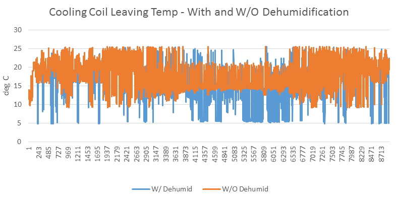
The project is a 400 square foot classroom "shoebox" that I'm running some infiltration sensitivity analysis on. Thus, I want to make sure I'm capturing the energy impact of dehumidification accurately. I'm using the HVACTemplate:System:Unitary template (everything is autosized), and I've input "CoolReheat" in the "! - Dehumidification Control Type" field. I've added a "ZoneControl:Humidistat" object that uses a compact schedule with a "percent" schedule type limits that uses 62.5 all year. After inspecting the expanded file, the AirLoopHVAC:Unitary:Furnace:HeatCool object has a "CoolReheat" designation in the "! - Dehumidification Control Type" and an additional reheat coil appeared. Everything looks good. So, why is the reheat and cooling energy increase so high? The scheme seems to be working, only 6% of all hours are above 62.5% relative humidity. I think the main problem is that with dehumidification, the cooling coil drops the temperature to 5 deg C (42 deg F) in some cases (see below graph). This seems unreasonable, and may be why there is so much reheat and coling energy, as actual systems would never really drop it below 55 deg F. I don't know how to control this, and I can't find a setpont manager that controls the subcooling routine for the dehumidification.
There appears to be a "!-minimum supply air temperature" field in the "SetpointMnager:SingleZone:Reheat" object set at 13, but it doesn't seem to have an effect. Is there a way to control this? Am I missing anything? Here is a link to the .idf in case it helps. https://drive.google.com/file/d/0B6aA... Thanks ahead of time for your help! |
| 2014-12-18 17:50:53 -0500 | received badge | ● Commentator |
| 2014-12-18 17:50:53 -0500 | commented answer | ZoneHVAC:FourPipeFanCoil Night Cycle Control? Michael - Fantastic information! I was definitely applying an on/off schedule to all of the components in the fancoil system. However, upon revisiting and ensuring that the fancoil, heating coil, and cooling coil all have always-on schedules --- and ensuring the fan object and availability manager's fan schedule field have the on/off schedules---- still no cycling at night. Here is a link to the .idf with only those objects included in case you want to take a look. |
| 2014-12-17 13:21:17 -0500 | commented answer | ZoneHVAC:FourPipeFanCoil Night Cycle Control? Annie, thanks for the info! I indeed had a schedule that included "0's" during unoccupied times. I was editing the expanded .idf, and I'm fairly certain everything had the right schedule, but I'll double check. I also did add the availability manager to the expanded object from the template (in the optional field in the ZoneHVAC:FourPipeFanCoil" expanded object) and still nothing. When reading the documentation in the inputoutputreference, it sounds like the nightcycle manager was designed for "central air systems," so I'm wondering if it will work with the fancoil object at all. |
| 2014-12-16 18:14:28 -0500 | commented answer | VAV System Not Converging Thanks for the information and reply! Some notes:
|
| 2014-12-15 18:21:52 -0500 | asked a question | ZoneHVAC:FourPipeFanCoil Night Cycle Control? Hello all - I'm modeling zonal fan coil units (constant fan, variable flow) with a dedicated outside air system, and I was wondering if there is any way to get night cycle control? I'm using the template objects, and there is no field for night cycle control. I can swap out the availabilitymanager:scheduled for an availabilitymanager:nightcycle in the DOAS airloop post-expansion, but it doesn't work. I've also noticed that there is an additional field in the ZoneHVAC:FourPipeFanCoil that isn't typically there. It is a field that asks for an availability manager list. However, upon creating a list with the appropriate night cycle manager, still nothing. I thought maybe it was because it was using a fan:constantvolume and not a fan:onoff, but that didn't work either. Is it possible, and if so, how? Thanks for your time and help! |
| 2014-12-15 12:57:43 -0500 | commented answer | Error Hard Sizing DX Cooling Coils Thanks for the information! |
| 2014-12-15 12:56:21 -0500 | commented answer | Unmet Load Hours Linked to Cycling Run Time? That's a good guess, but the window is facing north.... |
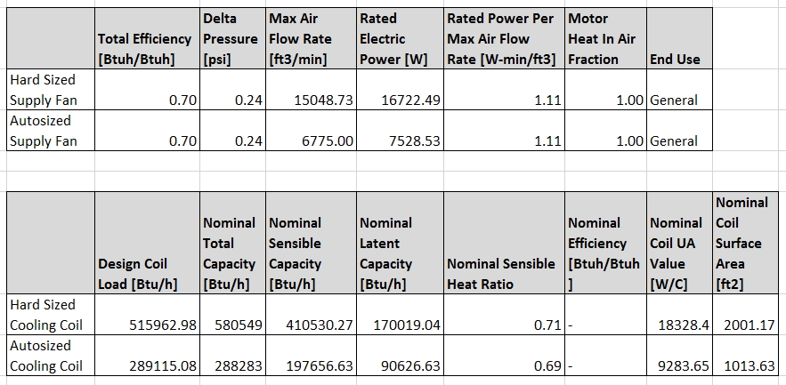
| 2014-12-15 12:50:06 -0500 | asked a question | VAV System Not Converging Simulation Community - I'm getting the following error when running my central VAV template system when running for only January: * Warning * SimHVAC: Maximum iterations (20) exceeded for all HVAC loops, at RUN PERIOD 1, 01/04 10:00 - 11:00 * ~~~ * The solution for one or more of the Air Loop HVAC systems did not appear to converge I'm modeling for LEED, and I'm getting this warning as ONLY when I hardsize the supply fan maximum flow rate in the hvactemplate:system:vav object according to the mechanical schedules for the project. The designed flow rates and capacities are about 2x the autosized rates, not sure if that would cause a problem. Here's a table that shows the fan and cooling coil sizes for both the autosizing baseline and the proposed case.
When using the output:diagnostics object to display extra warnings, it says that this particular air hander does not converge for temperature, energy, or mass flow rate. I've doubled the Maximum Hvac Iterations field in the ConvergenceLimits object to 50, but to no avail. Not sure if I need to adjust the temperature tolerance values in the building object. Any idea why this might be happening? Also Is this something that LEED is going to have an issue with? This causes a lot of warnings given it happens on during all times in the run period. |
| 2014-12-12 17:34:35 -0500 | asked a question | Error Hard Sizing DX Cooling Coils Simulation community - So I'm in the proposed modeling phase of LEED energy simulation, and I'm having some problems hard sizing some cooling coils for some split dx heat pump units serving technology closets. See error below, it looks like I'm inputting what I think is the total cooling capacity, but its calculating something else for the "Design Size Gross Rated Total Cooling Capacity." *** SizeDXCoil: Potential issue with equipment sizing for Coil:Cooling:DX:SingleSpeed DX-1 SYSTEM COOLING COIL * ~~~ * User-Specified Gross Rated Total Cooling Capacity [W] = 5274.00000 * ~~~ * differs from Design Size Gross Rated Total Cooling Capacity [W] = 3590.75955 * ~~~ * This may, or may not, indicate mismatched component sizes. So I must be missing an input, but since I'm just using the template objects so I think its pretty straightforward: - HVACTemplate:System:UnitaryHeatPump:AirToAir - HVACTemplate:Zone:Unitary I'm inputting a hard value for the Supply Air Maximum Flow Rate in the zone object, and I'm inputting a hard value for the "cooling supply air flow rate" and "Cooling Coil Capacity" fields in the system object. Upon checking out the coil:cooling:water object in the expanded .idf, it looks like everything is hardsized properly. Not sure what's going on here, but the slight reduction in capacity is causing unmet hours in the proposed case. Here are the text objects in case anyone is interested: HVACTemplate:Zone:Unitary, HVACTemplate:System:UnitaryHeatPump:AirToAir, |
| 2014-12-11 09:04:48 -0500 | commented answer | Unmet Load Hours Linked to Cycling Run Time? Thanks for the reply! Looking back at the mass flow rate and the outdoor air flow rate through the terminal, they both drop to 0 when the unit is cycled off, or during periods of no load during unoccupied times. It does seem like the loads are too high, but upon investigation all load are within reason, and the envelope was specified correctly. The zone analyzed in the charts above is a pretty small private office, but this is also happening in the classroom spaces throughout the project. Something must be specified incorrectly and I'm just not seeing it.... |
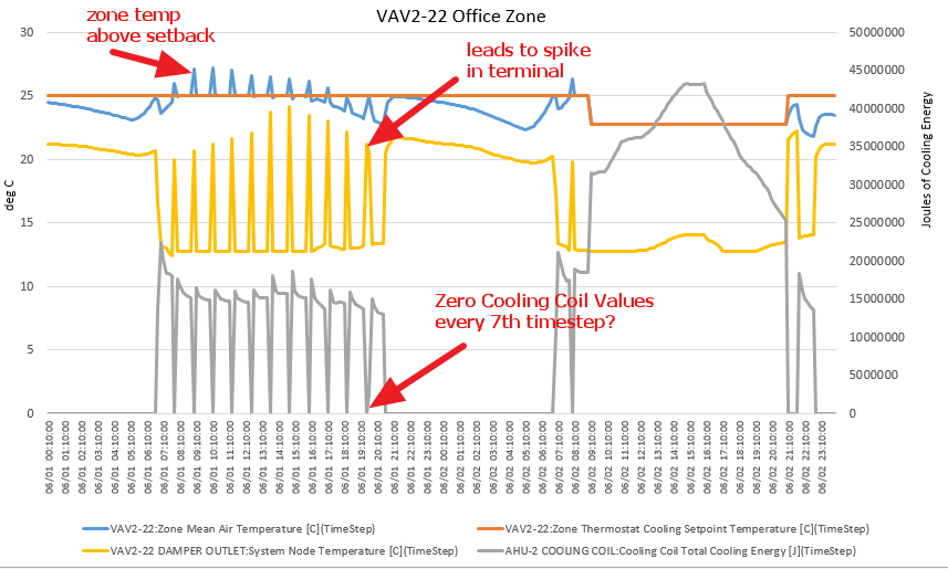
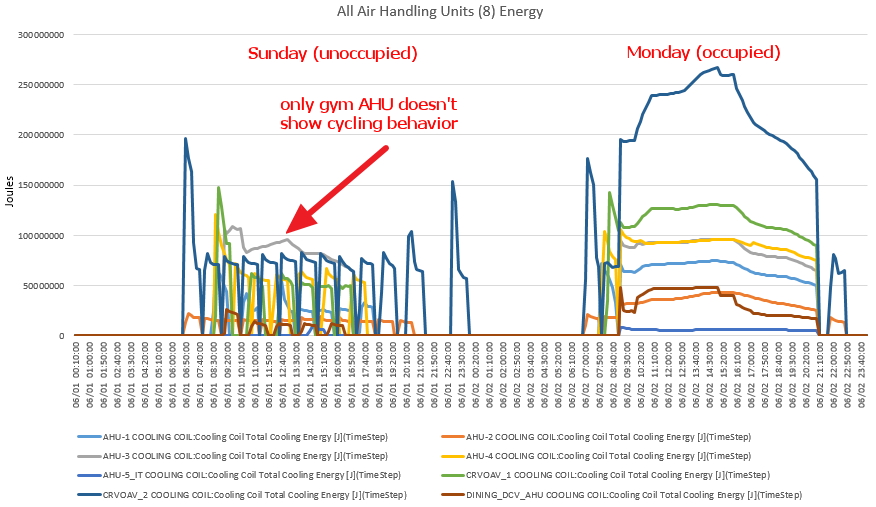
| 2014-12-04 12:28:24 -0500 | asked a question | Unmet Load Hours Linked to Cycling Run Time? Hi All - I'm investigating the inability of my EnergyPlus model to maintain setpoint during unoccupied hours. The short story: For my centralized VAV system (modeled through template objects), it appears that the AvailabilityManager:NightCycle control (cycleonany) is working properly for the time input into the "Cycling Run Time" field (currently set for 3,600 seconds - 1 hour). However, at the end of the cycle, the equipment drops to zero for one timestep, before cycling back on for an hour. Thus, the cooling coil energy will have values for 6 timesteps, then a zero, then values again for 6 timesteps, then zero, etc. This causes a drop in the VAV damper position and an increase supply air temperature (cooling) for said timestep, which allows the zone temp to float above the setback. I have no idea why it is doing this. Image of a Sunday and Monday - notice the cycling of the AHU-2 cooling coil energy and VAV terminal damper temperature.
The long story: 100+ zone, 2-story school. I used the HVACTemplateSystem:VAV, HVACTemplateZone:VAV, and constituent plant objects to model 6 air handling units for the various thermal zones of the building. The zone I'm analyzing is an office zone, and I double checked all internal loads to make sure nothing was out of whack. I've looked at the chilled water temperature leaving the plant and entering the air handling units, and the water temperatures look good. Its only the air temperatures leaving the coil that oscillate with the cycling behavior. I've tried to change the "Cycling Run Time field: in the AvailabilityManager:NightCycle, but the mysterious zero values still happen at the end. It's as if it takes a timestep for the system to realized it needs to come back on. Increasing the cycling run time to like 9 hours keeps the temperature in range, but subcools the space as the equipiment will run for that defined period, no matter what the temperature is. I'm running the model at 6 timesteps, which is the only reason I saw the mysterious zero values in the first place. Also, looking at the other 5 air handlers, they all exhibit the same cycling behavior - EXCEPT the gym zone. It is the only one that doesn't, but I'm fairly certain everything is modeled the same. Here's an image of all 8 air handling unit cooling coil energies, notice the cycling during the unoccupied times.
Link to the expanded .idf file - set up to run for 1 week in June, 6 timesteps. |
| 2014-11-05 09:41:47 -0500 | commented answer | aedg office hvac wshp doas - measure problems Thanks for the help! I changed the min max to reflect the mixed water loop operating range, i.e. 30 C for cooling, 18.3 for heating. When I run the simulation it gives me the severe error: * Severe * Plant temperatures are getting far too hot, check controls and relative loads and capacities * PlantLoop Inlet Node (SupplySide) does not have a Setpoint. * PlantLoop Inlet Node (DemandSide) does not have a Setpoint. * PlantLoop Outlet Node (SupplySide) does not have a Setpoint. * PlantLoop Outlet Node (DemandSide) does not have a Setpoint etc. etc. |
| 2014-11-05 09:31:10 -0500 | commented answer | aedg office hvac wshp doas - measure problems Thanks a ton for your comment! I tried to change the boiler/cooling tower configuration from in series to parallel in OS, and I also added a dual setpoint manager on the loop exit node (heating setpoint = 20 C, cooling = 30 C). However, i still get the same temperature out of range error. Not sure if I'm modeling it correctly in OS, but here's a picture of the configuration. I've also tried to run it without the single set point managers right after the cooling tower and boiler, still to no avail. |
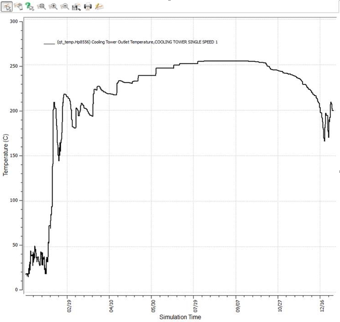
| 2014-11-03 11:03:13 -0500 | asked a question | aedg office hvac wshp doas - measure problems Simulation community - I'm having trouble using the "aedg office hvac wshp doas" measure. After creating a fairly simple model (5 zones, 5 stories) with pretty much all ASHRAE 90.1-2009 defaults, I attempted to use the aedg wshp whole building HVAC measure. It appears to work and specifies all of the equipment successfully, and even runs successfully, but my cooling unmet hours during occupied times are 4000+. Looking through the errors, it looks like these five are responsible: * Warning * GetSpecificHeatGlycol: Temperature is out of range (too high) for fluid [WATER] specific heat * * ~~~ * ..Called From:CalcHPCoolingSimple:SourceSideInletTemp,Temperature=[228.47], supplied data range=[0.00,125.00] * ~~~ ** Environment=NEW ORLEANS LAKEFRONT AP ANN CLG .4% CONDNS DB=>MWB, at Simulation time=08/21 00:00 - 01:00 * Warning * GetDensityGlycol: Temperature is out of range (too high) for fluid [WATER] density * * ~~~ * ..Called From:FindCompSPLoad,Temperature=[234.74], supplied data range=[0.00,100.00] * ~~~ ** Environment=NEW ORLEANS LAKEFRONT AP ANN CLG .4% CONDNS DB=>MWB, at Simulation time=08/21 00:00 - 01:00 * Warning * CoolingTower:SingleSpeed "COOLING TOWER SINGLE SPEED 1" * ~~~ * Cooling tower water outlet temperature (-0.24 C) is below the specified minimum condenser loop temp of 1.00 C * ~~~ * Environment=RUN PERIOD 1, at Simulation time=01/02 16:00 - 17:00 * Warning * GetSpecificHeatGlycol: Temperature is out of range (too low) for fluid [WATER] specific heat supplied values * * ~~~ * ..Called From:PlantLoopSolver::UpdateAnyLoopDemandAlterations,Temperature=[-0.24], supplied data range=[0.00,125.00] * ~~~ ** Environment=RUN PERIOD 1, at Simulation time=01/02 16:00 - 17:00 * Warning * GetDensityGlycol: Temperature is out of range (too low) for fluid [WATER] density * * ~~~ * ..Called From:FindCompSPLoad,Temperature=[-0.24], supplied data range=[0.00,100.00] * ~~~ ** Environment=RUN PERIOD 1, at Simulation time=01/02 16:00 - 17:00 Upon looking at the cooling tower outlet temperature, see image below, it spikes in February and stays in the unreal 200 deg celsius range. I'm not sure what is causing this, and I've even tried it on a single zone, even simpler model, and I get the same error and results. So I'm not sure if its something on my part or if there is an issue with the script. I've ran the "aedg office VHAC VAV with DX Cooling" and it works properly without any crazy temperature spikes or unmet hours.
Any help is greatly appreciated! Here is a link to a zipped folder with the osm and run files in case it's helpful. https://drive.google.com/file/d/0B6aA... Cheers, -jake |
| 2014-11-03 09:59:14 -0500 | commented answer | AddDaylightSensors.rb error David - One additional thing I noticed -- while the measure adds the control sensor, it does not connect the thermal zone and the daylight control together. The thermal zone in OS has a field for "Primary Daylighting Control Name," which gets autopopulated as long as you add the daylight control after you specify the thermal zone. With the measure, however, I noticed that it does not modify this field. I know you mentioned that it was a "proof of concept" measure, so this might not have been in the scope of the script. However, adding this functionality would provide great value. |
| 2014-10-29 09:03:44 -0500 | commented answer | AddDaylightSensors.rb error Thanks David for the prompt reply! I was indeed trying to run the measure before running the set window to wall area measure, so that totally makes sense. Even though this measure isn't as powerful as the AEDG ones, it is still very useful in automating the addition of daylight sensors in large models. Keep up the great work and thanks for your help! |
| 2014-10-29 09:02:18 -0500 | received badge | ● Scholar (source) |
| 2014-10-29 09:02:16 -0500 | received badge | ● Supporter (source) |
| 2014-10-29 07:42:55 -0500 | received badge | ● Student (source) |
| 2014-10-28 22:03:38 -0500 | asked a question | AddDaylightSensors.rb error When trying to use this script in the OpenStudio application as an "add measure now," I get the error that my spaces "has no exterior natural lighting. No sensor will be added." However, the spaces have a thermal zone, and have outdoor boundary conditions, so I'm not sure what qualifies as having exterior natural lighting. Here is a snippet of the code from the github site, but I can't interpret it, thanks for the help! https://github.com/NREL/OpenStudio-an... |