Question-and-Answer Resource for the Building Energy Modeling Community
First time here? Check out the Help page!
| 2024-04-12 14:32:22 -0500 | received badge | ● Popular Question (source) |
| 2024-04-12 05:38:18 -0500 | asked a question | DOAS is not autosized correctly DOAS is not autosized correctly I found a weird behaviour of autosizing. For DOAS, when a zone, some zones or all zones |
| 2024-04-10 05:00:02 -0500 | asked a question | EnergyPlus Crashes with Desiccant System EnergyPlus Crashes with Desiccant System I want to model desiccant system, but EnergyPlus crashes. There is not so much |
| 2024-04-08 10:34:38 -0500 | edited answer | Additional Lighting Power Allowance in new Appendix G I might be able to help you in part. 90.1-2019 has addenda: Addenda af, bc, cd, and db to Standard 90.1-2019 (November |
| 2024-04-06 03:29:41 -0500 | answered a question | Additional Lighting Power Allowance in new Appendix G I might be able to help you in part. 90.1-2019 has addenda: Addenda af, bc, cd, and db to Standard 90.1-2019 (November |
| 2024-04-06 03:29:41 -0500 | received badge | ● Rapid Responder (source) |
| 2024-04-02 22:08:24 -0500 | commented answer | What are "Initial Design" and "Design" in the summary report when running Coincident sizing? That issue is about air flow rate (air-side), isn't it? I always have an unreasonable result in plant coincident sizing |
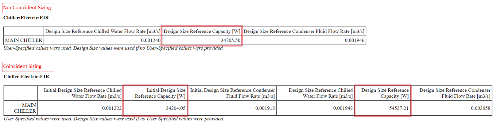
| 2024-04-02 19:48:48 -0500 | marked best answer | What are "Initial Design" and "Design" in the summary report when running Coincident sizing? When we run simulation with Coincident sizing, the html summary report shows Initial Design Capacity/Flow Rate/Power Consumption, etc. and Design Capacity/Flow Rate/Power Consumption, etc. I can't find clear explanation of these Initial Design values and Design values in I/O Reference and Engineering Reference. Does anyone know what they mean? I guess that Initial Design values are intermediate products during Coincident sizing and Design values are the final results of Coincident sizing which are used in annual simulation. However, I often get weird results. As an example, I show you the chiller sizing results of NonCoincident sizing and Coincident sizing with 5ZoneVAV-Pri-SecLoop.idf (V23-2-0) below.
The chiller capacity is Initial Design Capacity in Coincident sizing < Design Capacity in NonCoinsident sizing << Design Capacity in Coincident sizing. Due to the nature of Coincident sizing, it cannot be greater than NonCoincident sizing. I think Coincident sizing in EnergyPlus has many bugs and is unusable. Hopefully the bugs will be fixed at some point. As a first step, I want to know what Initial Design and Design mean. |
| 2024-04-02 19:48:34 -0500 | commented answer | What are "Initial Design" and "Design" in the summary report when running Coincident sizing? Thank you for your answer! I haven't checked Output Details and Examples. My guess was correct, and plant coincident si |
| 2024-04-02 04:25:45 -0500 | asked a question | How to Go back through the history of all my Votes on UnmetHours How to Go back through the history of all my Votes on UnmetHours I'm using the voting function on UnmetHours.com as book |
| 2024-04-02 02:52:43 -0500 | edited question | What are "Initial Design" and "Design" in the summary report when running Coincident sizing? What are "Initial Design" and "Design" in the summary report when running Coincident sizing? When we run simulation with |
| 2024-04-02 02:47:11 -0500 | asked a question | What are "Initial Design" and "Design" in the summary report when running Coincident sizing? What are "Initial Design" and "Design" in the summary report when running Coincident sizing? When we run simulation with |
| 2024-03-13 21:24:48 -0500 | commented answer | EMS control is off by one hour @Aaron Boranian Thank you for your reply. I misunderstood. Yes, both the first example and the second example work corre |
| 2024-03-13 21:17:35 -0500 | commented answer | EMS control is off by one hour @Aaron Boranian Thank you for your reply. I misunderstood. Yes, both the first example and the second example work corre |
| 2024-02-14 21:12:51 -0500 | commented question | Long elapsed times are not recorded correctly Posted issue as https://github.com/NREL/EnergyPlus/issues/10399 |
| 2024-02-14 01:35:17 -0500 | commented question | Time of Peak is not in Timestep increments @Aaron Boranian Interpolate to Timestep in Schedule:Day:Interval is set to "No" for the electric equipment schedule. So, |
| 2024-02-12 19:36:15 -0500 | commented question | Time of Peak is not in Timestep increments @Aaron Boranian I compared the end use at 04-SEP-08:09 shown in the html file and the end use at 04-SEP-08:08:34 shown i |
| 2024-02-12 19:35:57 -0500 | commented question | Time of Peak is not in Timestep increments @Aaron Boranian I compared the end use at 04-SEP-08:09 shown in the html file and the end use at 04-SEP-08:08:34 shown i |
| 2024-02-01 21:22:51 -0500 | edited question | Time of Peak is not in Timestep increments Time of Peak is not in Timestep increments A basic question. In the output files (html files), sometimes I see that Time |
| 2024-02-01 01:47:40 -0500 | answered a question | What are the solutions for modeling natural ventilation in summer? Why does no one mention ZoneVentilation:WindandStackOpenArea? It's the simplest model to try first, with no EMS or AFN, |
| 2024-01-31 20:38:41 -0500 | edited answer | "Plant flows do not resolve" with multiple variable primary pumps Not an answer. The severe error has not yet been resolved. As I could not reproduce the the error with ExampleFiles, I |
| 2024-01-31 03:51:31 -0500 | edited question | Time of Peak is not in Timestep increments Time of Peak is not in Timestep increments A basic question. In the output files (html files), sometimes I see that Time |
| 2024-01-31 03:50:52 -0500 | asked a question | Time of Peak is not in Timestep increments Time of Peak is not in Timestep increments A basic question. In the output files (htmls files), sometimes I see that Tim |
| 2024-01-23 23:57:41 -0500 | answered a question | How to Access the Building Model from Example file You can see the dxf file after running the simulation, and you can open it in the 3D modelling tools (Rhino, SketchUp, e |
| 2024-01-23 23:57:41 -0500 | received badge | ● Rapid Responder (source) |
| 2024-01-21 21:54:03 -0500 | edited answer | DesignSpecification:OutdoorAir ProportionalControlBasedOnOccupancySchedule method ProportionalControlBasedOnOccupancySchedule does not work. You can raise the issue (https://github.com/NREL/EnergyPlus/i |
| 2024-01-14 19:44:17 -0500 | commented answer | CentralHeatPumpSystem examples - modes 4/5? @alex j Please report bugs here. |
| 2024-01-10 18:47:42 -0500 | commented answer | CentralHeatPumpSystem examples - modes 4/5? @alex j My results on 1 Jan are quite different from the Screenshot your attached. I would appreciate it if you could sh |
| 2024-01-09 17:30:22 -0500 | received badge | ● Self-Learner (source) |
| 2024-01-06 22:23:07 -0500 | received badge | ● Rapid Responder (source) |
| 2024-01-06 22:23:07 -0500 | answered a question | Import idf file to designbuilder software Have you read EnergyPlus Version Compatibility? The latest DesignBuilder is compatible with EnergyPlus v9.4. You shoul |
| 2024-01-06 07:46:34 -0500 | answered a question | CentralHeatPumpSystem examples - modes 4/5? However the CentralHeatPump only seemed to go to mode 1,2,3... not mode 4 or 5. I just ran CentralChillerHeaterSyst |
| 2024-01-04 21:47:14 -0500 | commented answer | Selecting baseline HVAC system (ASHRAE 90.1 2010) @raheel LEED Certification Reviewers vary greatly in their knowledge levels and there is no uniform interpretation of re |
| 2024-01-04 21:32:46 -0500 | commented answer | RoomAirModel exhaust temperature offset does not affect exhaust heat transfer? @Jamie Sullivan I supplemented my answer a bit. |
| 2024-01-04 21:32:09 -0500 | commented answer | RoomAirModel exhaust temperature offset does not affect exhaust heat transfer? Ok, you have already modelled the make-up air (fresh air ventilation). What are your settings of RoomAirModelType? I c |
| 2024-01-04 21:31:45 -0500 | edited answer | RoomAirModel exhaust temperature offset does not affect exhaust heat transfer? Are you using Balanced Exhaust Fraction Schedule Name? I guess your zone has HVAC system other than Fan:ZoneExhaust. |
| 2024-01-04 02:29:45 -0500 | answered a question | Troubleshooting Advanced Dehumidification and Water-to-Air Heat Recovery Modeling Issue This is not a perfect answer. There are many problems with your model, and this only points out some of them. You shoul |
| 2024-01-04 00:17:08 -0500 | answered a question | Coil:Heating:DX:MultiSpeed - rated waste heat fraction of power input Coil:Heating:DX:MultiSpeed The rated waste heat fraction is needed to calculate how much waste heat is available at |
| 2024-01-04 00:17:08 -0500 | received badge | ● Rapid Responder (source) |
| 2024-01-03 21:28:58 -0500 | commented answer | RoomAirModel exhaust temperature offset does not affect exhaust heat transfer? Ok, you already have modelled the make-up air (fresh air ventilation). What are your settings of RoomAirModelType? I c |
| 2024-01-03 21:28:20 -0500 | commented answer | RoomAirModel exhaust temperature offset does not affect exhaust heat transfer? Ok, you already have modelled the make-up air (fresh air ventilation). What are your settings of [RoomAirModelType](htt |
| 2024-01-03 21:27:35 -0500 | commented answer | RoomAirModel exhaust temperature offset does not affect exhaust heat transfer? Ok, you already have modelled the make-up air (fresh air ventilation). What are your settings of [RoomAirModelType](htt |
| 2023-12-30 08:22:23 -0500 | edited answer | Water Heater Efficiency per Table 7.8 of ASHRAE 90.1-2010 ASHRAE90.1-2010 specifies two requirements for Gas stoarge water heaters in TABLE 7.8. One is Et = 80%. The other is SL |
| 2023-12-30 02:41:07 -0500 | edited answer | Water Heater Efficiency per Table 7.8 of ASHRAE 90.1-2010 ASHRAE90.1-2010 specifies two resuirements for Gas stoarge water heaters in TABLE 7.8. One is Et = 80%. The other is SL |
| 2023-12-30 02:18:33 -0500 | answered a question | Water Heater Efficiency per Table 7.8 of ASHRAE 90.1-2010 ASHRAE90.1-2010 specifies two resuirements for Gas stoarge water heaters in TABLE 7.8. One is Et = 80%. The other is SL |
| 2023-12-30 02:18:33 -0500 | received badge | ● Rapid Responder (source) |
| 2023-12-28 04:36:16 -0500 | edited answer | Selecting baseline HVAC system (ASHRAE 90.1 2010) According to your description, it seems that only the outdoor air is heated by TFA (Treated Fresh Air Unit) and there is |
| 2023-12-28 02:33:08 -0500 | edited answer | Selecting baseline HVAC system (ASHRAE 90.1 2010) According to your description, it seems that only the outdoor air is heated by TFA (Treated Fresh Air Unit) and there is |