Question-and-Answer Resource for the Building Energy Modeling Community
First time here? Check out the Help page!
| 2022-12-03 22:52:07 -0500 | received badge | ● Popular Question (source) |
| 2022-11-04 12:06:56 -0500 | asked a question | sketchup space boundary overlaps other spaces but it is not clear why sketchup space boundary overlaps other spaces but it is not clear why I'm new to using sketchup as a geometry tool for O |
| 2020-07-08 10:48:05 -0500 | received badge | ● Notable Question (source) |
| 2020-03-19 17:09:24 -0500 | received badge | ● Popular Question (source) |
| 2018-04-09 16:15:35 -0500 | received badge | ● Self-Learner (source) |
| 2016-11-04 18:47:24 -0500 | asked a question | is it possible to model roof reflectance in OS? Are there fields in OS to input roof material reflectance/emittance for modeling cool roofs? |
| 2016-11-04 12:12:41 -0500 | commented answer | How do I create part load EER curve for DX cooling in OS? Thank you. How do I go about matching the part load curve data fields in OS to my actual equipment? I have actual vendor data for my equipment with an EER of 10.2 and an IEER of 16.4. My understanding is that I would input a value of 2.99 for COP (=10.2/3.41) and then I need to input part load curve data to approximate the IEER of 16.4. |
| 2016-11-02 21:27:43 -0500 | asked a question | How do I create part load EER curve for DX cooling in OS? Rather than using IEER values for DX equipment efficiency, I understand that we must convert EER to COP (COP=EER/3.41) and then must create a part load curve. Are there input fields in OS that allow for this or do I need to work directly in Eplus? Also if I have manufacturer information on IEER, but presumably that is not valid, so how do I go about translating the vendor information into an Eplus-simulated part load efficiency curve? |
| 2016-11-02 21:21:18 -0500 | commented answer | What should I use to calculate COP? EER or IEER? Oops. Sorry, will do. |
| 2016-11-02 18:05:44 -0500 | answered a question | What should I use to calculate COP? EER or IEER? From the discussion above, I understand that we must convert EER to COP (COP=EER/3.41) and then must create a part load curve. Are there input fields in OS that allow for this or do I need to work directly in Eplus? Also if I have manufacturer information on IEER, but presumably that is not valid, so how do I go about translating the vendor information into an Eplus-simulated part load efficiency curve? |
| 2015-12-12 23:21:51 -0500 | commented answer | Trouble-shooting unmet heating hours on EnergyPlus I think I posted the wrong model, but i am having the same problem with boiler autosizing in the one I posted as the one I meant to post. Either way if you are able to solve the boiler sizing issue please let me know. Thanks again. |
| 2015-12-12 11:41:03 -0500 | commented answer | Trouble-shooting unmet heating hours on EnergyPlus That's both good and bad news. Last I ran it I had around 6000 unmet hours and yes all were due to boiler capacity which is frustrating because I'm autosizing the boiler. I've spent a work week trying to find the issue. Thanks very much for your help. |
| 2015-12-10 13:00:48 -0500 | commented answer | Trouble-shooting unmet heating hours on EnergyPlus Thanks @aparker . Here is the Google Drive link to my: OSM file: https://drive.google.com/file/d/0B610... DDY file: https://drive.google.com/file/d/0B610... EPW file: https://drive.google.com/file/d/0B610... |
| 2015-12-07 14:43:06 -0500 | commented answer | Trouble-shooting unmet heating hours on EnergyPlus I'm really struggling to figure out where my problem is. Is it appropriate to ask if anyone in the community would be willing to look at my OS model and help me troubleshoot my inputs? My VAV's are all opening up to 100% and my heating flowrate is tracking my fume hood usage schedule. My boiler PLR is not always at 100% and often seems to be too low during the peak heating season. My zones do not want to heat. I get an error that says that my calculated zone heating load is zero. I don't get it. I can post my model, but I'm not sure where/how to post it. |
| 2015-12-05 03:16:17 -0500 | commented answer | Trouble-shooting unmet heating hours on EnergyPlus I figured out how to do the graphing. Explanation here for anyone else reading this thread that may not know how. I am using a BCL measure called "AddOutputVariable". Using the eplusout.rdd file I looked up the variable names for what you suggested I graph and inserted those names as arguments in the measure. Then the graphing is done by ResultsViewer. I will post another comment with my findings after I review the graphs. |
| 2015-12-04 15:09:51 -0500 | commented answer | Trouble-shooting unmet heating hours on EnergyPlus Thanks.
1. Yes, all zones. I have two zones. Both lab areas.
2&4. Can you advise how to graph the variables you mentioned? My model is deliberately set to force 100% OA at all times because it is a lab. I have zone exhaust which operates on a variable flow schedule and my supply air is trying to track the zone exhaust. My minimum flow fraction for my zone vav box is set to 1 and my design flow is set to follow the same schedule that my zone exhaust fans follow. |
| 2015-12-04 14:58:27 -0500 | commented answer | OS Zone Sizing Report Question I think there IS an issue of some sort with the zone reporting measure. The heating cfm from Energyplus and from OS is correct but way low in the zone reporting measure. |
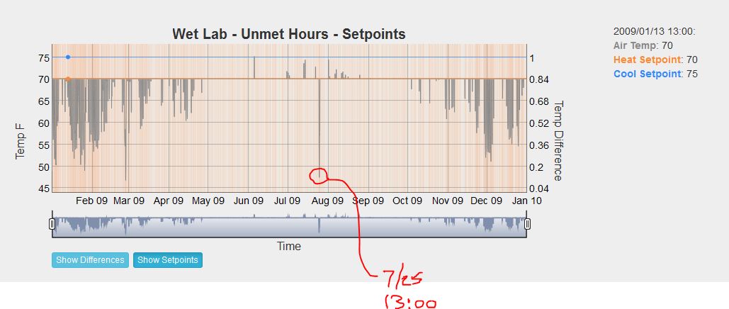
| 2015-12-03 18:57:27 -0500 | asked a question | Trouble-shooting unmet heating hours on EnergyPlus I am using a measure which helps me troubleshoot unmet hours. I have satisfied all of the prompts but I still have about 1000 unmet heating hours. Looking at the helpful graphs and ResultsViewer, I see an interesting pattern that I want to ask about. This graph is for one of two lab zones on my VAV with Reheat HVAC system. Both zones look identical.
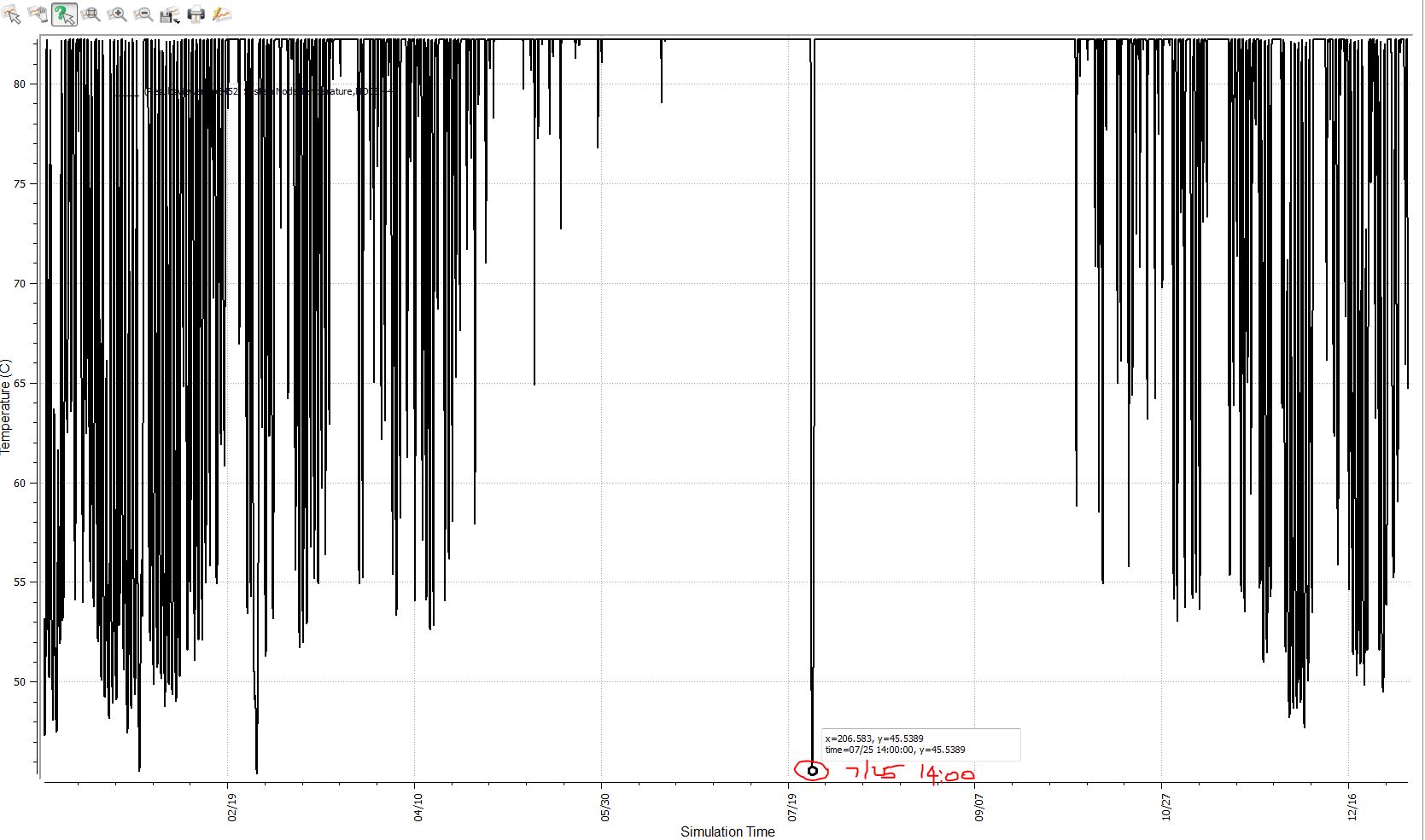
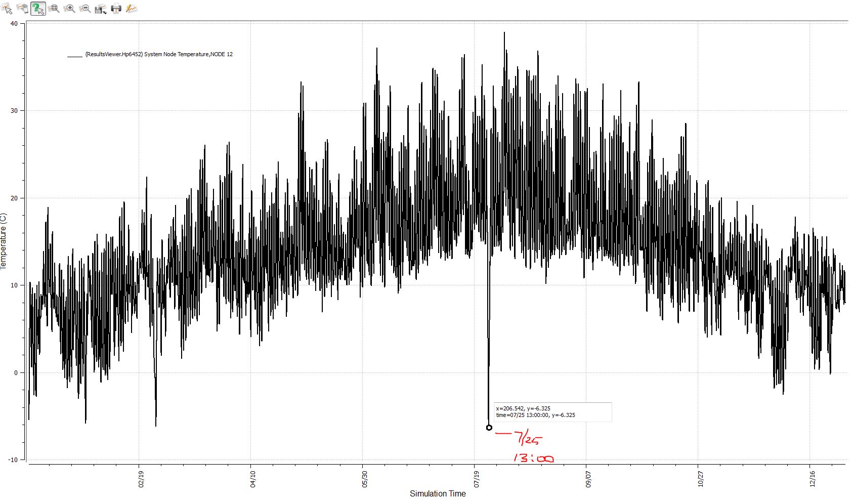
For whatever reason, my zone does not want to heat very well and the "valleys" of my actual zone temperature appear to align very well with patterns in ResultsViewer that I see for my boiler supply temperature which is set via a setpoint schedule that I have made flat year-round at 180 degrees F as well as outside air temperature. See below. The middle valley occurs on July 27 at 13:00 (14:00 for OA temp, but why would I have -6 degrees C (21.2 deg F) OA in the dead of Summer? I have made certain that I am using .EPW and .DDY files for Livermore, CA. Hot Water Supply Temperature Graph
Outdoor Air Temperature Graph
Can anyone surmise what the heck is going on here? I don't understand why my actual zone temperatures top-out at my heating setpoint instead of bottoming-out at my heating setpoint. Very weird. |
| 2015-12-03 18:24:11 -0500 | commented answer | Zone Exhaust Fan Motor Heat As a program enhancement, it would be nice if there was a field or two to specify where the heat should go. |
| 2015-12-03 18:22:24 -0500 | received badge | ● Scholar (source) |
| 2015-12-03 15:25:22 -0500 | asked a question | Zone Exhaust Fan Motor Heat Does anyone know if the motor heat for a Fan:ZoneExhaust goes directly into the zone, into the exhaust airstream, or if it is a throw-away load used only for electrical loading? It seems like there should be a way to dictate where the motor heat should go. I am hoping that it is NOT getting added into my zones as a cooling load because in reality my exhaust fans are outside the building on the roof and the motor is outside the exhaust airstream too so I would not want that motor heat to warm up my exhaust air either in the model since I want to accurately model heat recovery. |
| 2015-12-03 14:29:28 -0500 | answered a question | OS Zone Sizing Report Question I figured out at least part of my problem. When I changed my simplified model from one with a Packaged Rooftop VAV with Reheat to one with Ideal Air Loads, I forgot to change my zone cooling and heating design airflow method to DesignDay. I had previously set it to Flow/Zone. I still do not know why the user design heating load was so high though, nor why the user design airflow was so low by comparison. Now my user design heating load is showing up as 18,440 BTUH (which is about 10% higher than the answer I get by multiplying the BTUH/SF by the zone floor area.). Seems reasonable. The user design airflow is still coming out low by comparison. If my design heating supply air temperature is 105 degrees F and I'm trying to maintain 70 degrees F setpoint on my heating design day, the associated zone airflow in heating for a user design heating load of 18,440 BTUH should be around 488 cfm. The zone report now gives only 8.12 cfm as user design airflow in heating, which is too low. |
| 2015-12-03 14:09:19 -0500 | commented answer | OS Zone Sizing Report Question Agreed. Though I still do not understand what is driving the large difference between calculated heating load of 16,731 BTUH and the user design load of 418,480 BTUH. |
| 2015-12-02 21:43:48 -0500 | commented question | OS Zone Sizing Report Question I found this post about a similar question link. Still scratching my head though. |
| 2015-12-02 19:36:49 -0500 | asked a question | OS Zone Sizing Report Question I have a question about what "User Design Load" means in the Zone Sizing Report (created using a BCL measure in Openstudio) linked here. Working to troubleshoot why my boiler for a Packaged Rooftop VAV with Reheat system is not being properly autosized, I decided to save out a copy of my model and switch back to Ideal Air Loads. Attached is a copy of the output for one of my zones. Can anyone advise where I might have input something that would influence a user design load? I have a similar question about User Design Airflow. The values given (see attached screenshot) for both cooling and heating User Design Airflows seem very low in comparison to the Peak Heating Load and Peak Cooling Load. |
| 2015-12-02 12:04:46 -0500 | commented answer | boiler sizing conundrum in OS Thanks. This is a big help. Your guess was not the reason, exactly. What I found was a problem with my setpoint schedule and also I had input 55 degrees F as the sizing discharge temperature for my central heating coil. The link you provided was also very helpful. |
| 2015-12-02 12:04:46 -0500 | received badge | ● Commentator |
| 2015-12-01 18:55:05 -0500 | asked a question | boiler sizing conundrum in OS I am looking for some guidance. I have set up a model for a Packaged Rooftop VAV with Reheat and I have set all of my sizing to Autosized. My boiler supplies hot water to a heating coil inside my AHU and to two Reheat coils, one at each VAV box. My simulation comes up with a boiler that I estimate to be about 1/4 of the proper capacity AND I also have many unmet hours in heating. I've been trying to troubleshoot my model and am using a measure that provides good flow and temperature data at select nodes. My AHU has a setpoint manager on the supply air downstream of my heating coil which controls my heating coil (and DX cooling coil in sequence) to maintain a fixed supply air temperature. My node diagnostics seem to indicate that the supply air temperature downstream of my setpoint manager is colder than my setpoint during the design winter day. I also have a setpoint manager on the downstream side of my hot water boiler which also does not seem to be hot enough (setpoint=180 degrees F and actual temperature is around 125 degrees F). All of this tells me that my OS inputs are making E+ undersize my boiler. Furthermore, just for fun I input a hard boiler capacity that is closer to my hand-estimated boiler size and my unmet heating hours went down significantly and my node diagnostics also indicated improvement. Are there some key areas of my model that spring to mind that could be causing E+ to undersize my boiler in Autosize mode? |
| 2015-12-01 13:29:01 -0500 | commented answer | How to Validate HVAC loop temperatures at each node in OS Thank you very much. This is very helpful. Hopefully it will help me figure out why my boiler and DX coil are undersized. |
| 2015-12-01 11:58:32 -0500 | asked a question | How to Validate HVAC loop temperatures at each node in OS I am troubleshooting my design boiler sizing and DX cooling coil sizing for my model built in OS. I am using a Packaged Rooftop VAV with Reheat in my model which is for a laboratory. Through input selections I am trying to make sure that economizer is not modelled since I want a 100% outdoor air system at all times. My 100% OA supply fan is intended to be balanced by my Zone Exhaust fans which are for fume hoods. I think I have the air systems set up correctly because my fans are all properly sized by E+ based on my inputs, but my coil loads (both DX and hot water) appear to all be undersized. I am suspecting that somehow the system might think it is still a recirculating system pulling back and mixing in some return air to "degrade" the inlet conditions away from extreme winter and extreme summer design day temperatures, hence undersizing my boiler and DX coil. Is there a way to drill down into the E+ output file(s) to identify the air temperatures and air enthalpies at each node of my air system so that I can see if I still have some settings that are incorrect in OS? I am not an E+ person (yet) so if there is a method I need a knowledgable person to spoon feed me the solution, if possible. Thanks!! FYI, for more information about how I've set up my model, see this link for a question I posted earlier. |
| 2015-11-30 14:59:21 -0500 | received badge | ● Teacher (source) |
| 2015-11-30 14:56:20 -0500 | answered a question | fume hood exhaust capacity modeling Please forgive the lengthy response in attempt to answer my own question, but I want to do so to draw out some constructive feedback from the community: Here's what I decided to try, but I am unsatisfied with the output results for my boiler and for my DX cooling coil which appear to come out undersized based on the constraints I have selected. I’ll explain more at the end. If others have a different opinion on how to approach this model, please chime in (note that if I do not mention a particular input field below it means I left the Openstudio default choices as is): I modeled two laboratory spaces each with 8 VAV fume hoods and assigned each space to its own thermal zone. I chose to use the Fan:ZoneExhaust, one per lab space. I made an hourly schedule for fume exhaust utilization as a percentage of total exhaust flow. Since each hood is worth 1200 cfm of exhaust at full flow and I have 8 hoods, I set the Maximum Flow Rate for each zone exhaust fan to 9600 cfm. I assigned my fume exhaust utilization schedule as "Flow Fraction Schedule Name", selected Coupled and Always On Discrete for my availability schedule. I left the "Balanced Exhaust Fraction Schedule Name" unassigned as my understanding is that if this field is left alone, E+ will attempt to balance the zone exhaust with supply air (Is this correct?). Next, I assigned my two lab zones to a Packaged DX Rooftop VAV with Reheat. For the Sizing:System Object under AirLoopHVAC for my Packaged DX Rooftop VAV with Reheat unit, I made the following choices: “Type of Load to Size On”=VentilationRequirement (I selected this as my first choice because I believe this must be the right selection for a fume exhaust-driven HVAC system, but ... (more) |
| 2015-11-25 19:27:04 -0500 | received badge | ● Editor (source) |
| 2015-11-25 19:23:56 -0500 | asked a question | fume hood exhaust capacity modeling I am struggling to correctly model a laboratory ventilation system with multiple VAV fume hoods in Openstudio. I have 8 hoods with vav sashes and I've made a schedule similar to a lighting schedule that I want to apply to the peak fume exhaust rate to simulate a variable number of open hood sashes through a typical day. I am using a VAV air handler with DX cooling coil and hot water heating coil in the AHU and HW reheat coils for the lab zones. Each lab contains 8 hoods and each hood has a maximum of 1200 cfm of exhaust. I am using a manifolded exhaust system rather than one exhaust fan per hood. I am constraining my exhaust system to a maximum flow of 19200 cfm and a minimum flow of 15000 cfm so that I keep a minimum exhaust stack velocity (so not a large degree of exhaust fan energy savings from VAVh oods, but I will save a lot on makeup air conditioning). I placed a variable speed exhaust fan on the exhaust node at the air handling unit. Do I hard size the exhaust fan min and max cfm and apply the fume hood schedule? Do I apply the same hard cfm settings and/or schedule to my supply fan? Also because I have no return duct I turned off economizer in the ventilation control object for the ahu. I also noticed that there are some zone flowrate control options for each of my lab zones but I don't know whether to use those or the fan flow controls or both. |
| 2015-11-24 17:57:11 -0500 | commented answer | How do I add a downloaded measure into OS? Thanks, though I wanted to know how to add a measure that I had downloaded externally. I figured it out eventually though. The measure and it's subfolders once downloaded, typically as a zip file to preserve the required file structure, should get unzipped and placed in the C:\Users\Username\OpenStudio\Measures folder. Once placed there, click the "Sync Project Measures with Library" button and OS will recognize the measure in the library and it can be dragged and dropped within the OS Measures table. |
| 2015-11-24 15:31:42 -0500 | asked a question | How do I add a downloaded measure into OS? I just downloaded a measure from BCL in the form of a zip file. Now how to I add it into OS on the measures tab? Is this just a matter of placing the unzipped folders for the measure into the proper directory on my computer so that the measure is visible in the library within OS so that I can drag and drop? |

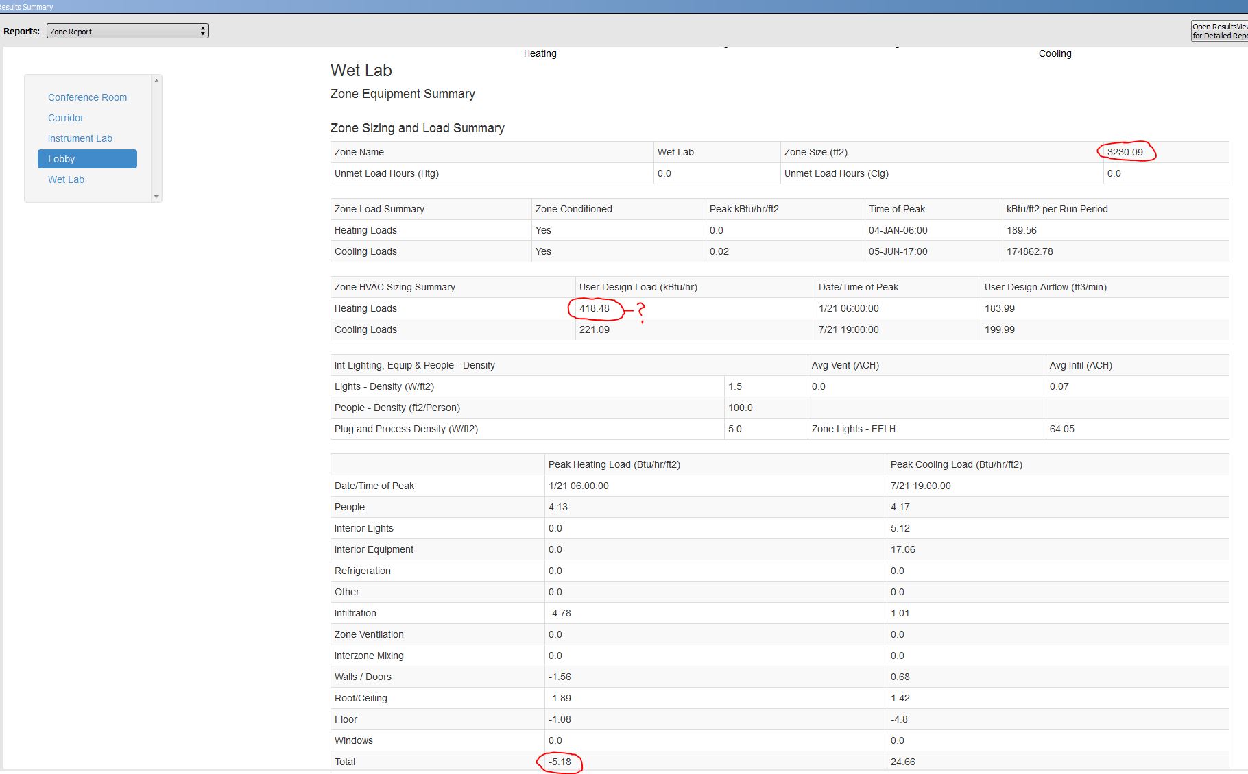 . Under Zone HVAC Sizing Summary, I see a heating load of 418,480 BTUH for my zone as a "User Design Load". I have no idea where I've specified any loads directly in my OS settings. Two other data points worth noting are my Peak Heating Load of 5.18 BTUH/ft2 and square footage of 3230 which when multiplied together give 16,731 BTUH which makes more sense for an ideal air heating load consisting of walls, roof, floors and etcetera.