Question-and-Answer Resource for the Building Energy Modeling Community
Get started with the Help page
Ask Your Question

Revision history [back]

click to hide/show revision 1
initial version

Demand Controlled Ventilation (DCV) not reaching CO2 Concentration Setpoint

Hello everyone,

I am trying to model an AirLoop with DCV in openstudio. I've seen it is only reachable via EnergyPlus (v23.20 used) so that is what I am doing right now. I have set the following configurations on the IDF:

ZoneControl:ContaminantController,
    DCV_900ppm,              !- Name
    Thermal Zone: L01_Multipurpose Room 1,  !- Zone Name
    Always On,               !- Carbon Dioxide Control Availability Schedule Name
    CO2_900ppm_setpoint;     !- Carbon Dioxide Setpoint Schedule Name

Controller:OutdoorAir,
    Controller Outdoor Air 1,!- Name
    Node 93,                 !- Relief Air Outlet Node Name
    Node 32,                 !- Return Air Node Name
    Node 37,                 !- Mixed Air Node Name
    Outboard OA Node,        !- Actuator Node Name
    0,                       !- Minimum Outdoor Air Flow Rate {m3/s}
    100000,                  !- Maximum Outdoor Air Flow Rate {m3/s}
    NoEconomizer,            !- Economizer Control Type
    ModulateFlow,            !- Economizer Control Action Type
    28,                      !- Economizer Maximum Limit Dry-Bulb Temperature {C}
    64000,                   !- Economizer Maximum Limit Enthalpy {J/kg}
    ,                        !- Economizer Maximum Limit Dewpoint Temperature {C}
    ,                        !- Electronic Enthalpy Limit Curve Name
    -100,                    !- Economizer Minimum Limit Dry-Bulb Temperature {C}
    NoLockout,               !- Lockout Type
    FixedMinimum,            !- Minimum Limit Type
    ,                        !- Minimum Outdoor Air Schedule Name
    ,                        !- Minimum Fraction of Outdoor Air Schedule Name
    ,                        !- Maximum Fraction of Outdoor Air Schedule Name
    Controller Mechanical Ventilation 1,  !- Mechanical Ventilation Controller Name
    ,                        !- Time of Day Economizer Control Schedule Name
    No,                      !- High Humidity Control
    ,                        !- Humidistat Control Zone Name
    ,                        !- High Humidity Outdoor Air Flow Ratio
    Yes,                     !- Control High Indoor Humidity Based on Outdoor Humidity Ratio
    BypassWhenWithinEconomizerLimits,  !- Heat Recovery Bypass Control Type
    InterlockedWithMechanicalCooling;  !- Economizer Operation Staging

Controller:MechanicalVentilation,
    Controller Mechanical Ventilation 1,  !- Name
    Always On Discrete,      !- Availability Schedule Name
    Yes,                     !- Demand Controlled Ventilation
    IndoorAirQualityProcedure,  !- System Outdoor Air Method
    ,                        !- Zone Maximum Outdoor Air Fraction {dimensionless}
    ...
    _Common Zones,           !- Design Specification Outdoor Air Object Name 4
    ,                        !- Design Specification Zone Air Distribution Object Name 4
    Thermal Zone: L01_Multipurpose Room 1,  !- Zone or ZoneList 5 Name
    _Multipurpose,           !- Design Specification Outdoor Air Object Name 5

    ,                        !- Design Specification Zone Air Distribution Object Name 5

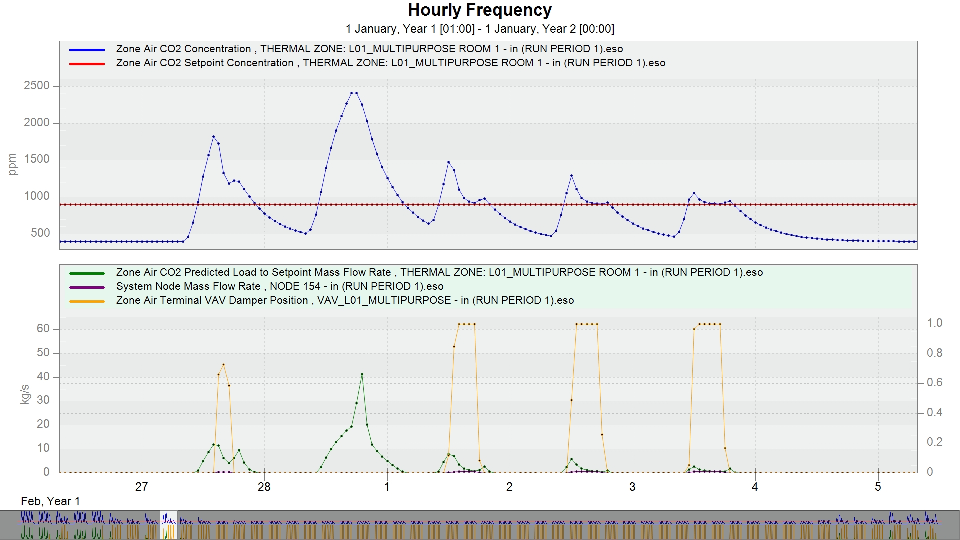
With that configuration I get the following graphs:

It seems I cannot upload images :(

What I got is the following:

  • 900ppm setpoint is reach in almost all year but the coldest ones (december and january)
  • Max Air Flow in the Zone Air Termina is not reached at any point. In that cold days ventilation is 0, so that is the point of having so high CO2 levels (2400ppm instead of 900ppm setpoint)

I have checked the following:

  • <zone air="" co2="" predicted="" load="" to="" setpoint="" mass="" flow="" rate=""> is showing proper values when DCV activated (YES)
  • I have tried turning DCV off and <zone air="" co2="" predicted="" load="" to="" setpoint="" mass="" flow="" rate=""> is changed to 0, but results on Air Terminals Flow Rates are the same. It seems the DCV is not controlling Flow Rate with the Setpoint.

If anyone knows how to fix this please help me :)

Demand Controlled Ventilation (DCV) not reaching CO2 Concentration Setpoint

Hello everyone,

I am trying to model an AirLoop with DCV in openstudio. I've seen it is only reachable via EnergyPlus (v23.20 used) so that is what I am doing right now. I have set the following configurations on the IDF:

ZoneControl:ContaminantController,
    DCV_900ppm,              !- Name
    Thermal Zone: L01_Multipurpose Room 1,  !- Zone Name
    Always On,               !- Carbon Dioxide Control Availability Schedule Name
    CO2_900ppm_setpoint;     !- Carbon Dioxide Setpoint Schedule Name

Controller:OutdoorAir,
    Controller Outdoor Air 1,!- Name
    Node 93,                 !- Relief Air Outlet Node Name
    Node 32,                 !- Return Air Node Name
    Node 37,                 !- Mixed Air Node Name
    Outboard OA Node,        !- Actuator Node Name
    0,                       !- Minimum Outdoor Air Flow Rate {m3/s}
    100000,                  !- Maximum Outdoor Air Flow Rate {m3/s}
    NoEconomizer,            !- Economizer Control Type
    ModulateFlow,            !- Economizer Control Action Type
    28,                      !- Economizer Maximum Limit Dry-Bulb Temperature {C}
    64000,                   !- Economizer Maximum Limit Enthalpy {J/kg}
    ,                        !- Economizer Maximum Limit Dewpoint Temperature {C}
    ,                        !- Electronic Enthalpy Limit Curve Name
    -100,                    !- Economizer Minimum Limit Dry-Bulb Temperature {C}
    NoLockout,               !- Lockout Type
    FixedMinimum,            !- Minimum Limit Type
    ,                        !- Minimum Outdoor Air Schedule Name
    ,                        !- Minimum Fraction of Outdoor Air Schedule Name
    ,                        !- Maximum Fraction of Outdoor Air Schedule Name
    Controller Mechanical Ventilation 1,  !- Mechanical Ventilation Controller Name
    ,                        !- Time of Day Economizer Control Schedule Name
    No,                      !- High Humidity Control
    ,                        !- Humidistat Control Zone Name
    ,                        !- High Humidity Outdoor Air Flow Ratio
    Yes,                     !- Control High Indoor Humidity Based on Outdoor Humidity Ratio
    BypassWhenWithinEconomizerLimits,  !- Heat Recovery Bypass Control Type
    InterlockedWithMechanicalCooling;  !- Economizer Operation Staging

Controller:MechanicalVentilation,
    Controller Mechanical Ventilation 1,  !- Name
    Always On Discrete,      !- Availability Schedule Name
    Yes,                     !- Demand Controlled Ventilation
    IndoorAirQualityProcedure,  !- System Outdoor Air Method
    ,                        !- Zone Maximum Outdoor Air Fraction {dimensionless}
    ...
    _Common Zones,           !- Design Specification Outdoor Air Object Name 4
    ,                        !- Design Specification Zone Air Distribution Object Name 4
    Thermal Zone: L01_Multipurpose Room 1,  !- Zone or ZoneList 5 Name
    _Multipurpose,           !- Design Specification Outdoor Air Object Name 5

    ,                        !- Design Specification Zone Air Distribution Object Name 5

With that configuration I get the following graphs:

It seems I cannot upload images :(

image description February last week on the graph

And if toggle DCV to NO <zone air="" co2="" predicted="" load="" to="" setpoint="" mass="" flow="" rate=""> changes to zero but the rest of the parameters remain the same.

What I got is the following:

  • 900ppm setpoint is reach in almost all year but the coldest ones (december and january)(december-february)
  • Max Air Flow in the Zone Air Termina is not reached at any point. In that cold days ventilation is 0, so that is the point of having so high CO2 levels (2400ppm instead of 900ppm setpoint)

I have checked the following:

  • <zone air="" co2="" predicted="" load="" to="" setpoint="" mass="" flow="" rate=""> is showing proper values when DCV activated (YES)
  • I have tried turning DCV off and <zone air="" co2="" predicted="" load="" to="" setpoint="" mass="" flow="" rate=""> is changed to 0, but results on Air Terminals Flow Rates are the same. It seems the DCV is not controlling Flow Rate with the Setpoint.

If anyone knows how to fix this please help me :)