I am simulating a hot water plant with WaterHeater:HeatPump:PumpedCondenser. I have found the water heater stops is operating after 4 days from abnormally when the start of the running period.
I think inlet air temperature is less than what it is something related to the input "Minimum Inlet Air Temperature for Compressor Operation". specified.
Currently it is set at the allowable minimum (-5 degree C) and C). When the outdoor air temperature does fall falls below -5C on the 5th day. day, the water coil of heat pump somehow can operate at full capacity as the first graph below.
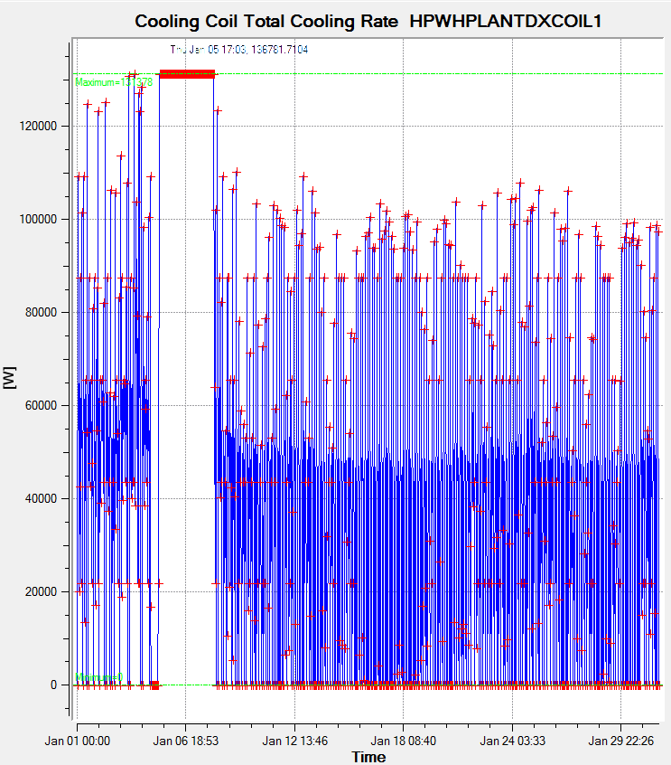
The tank temperature is still dropping regardless of the heat pumps will not restart when transfer from source side.
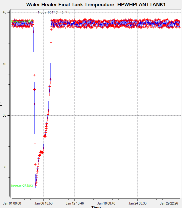
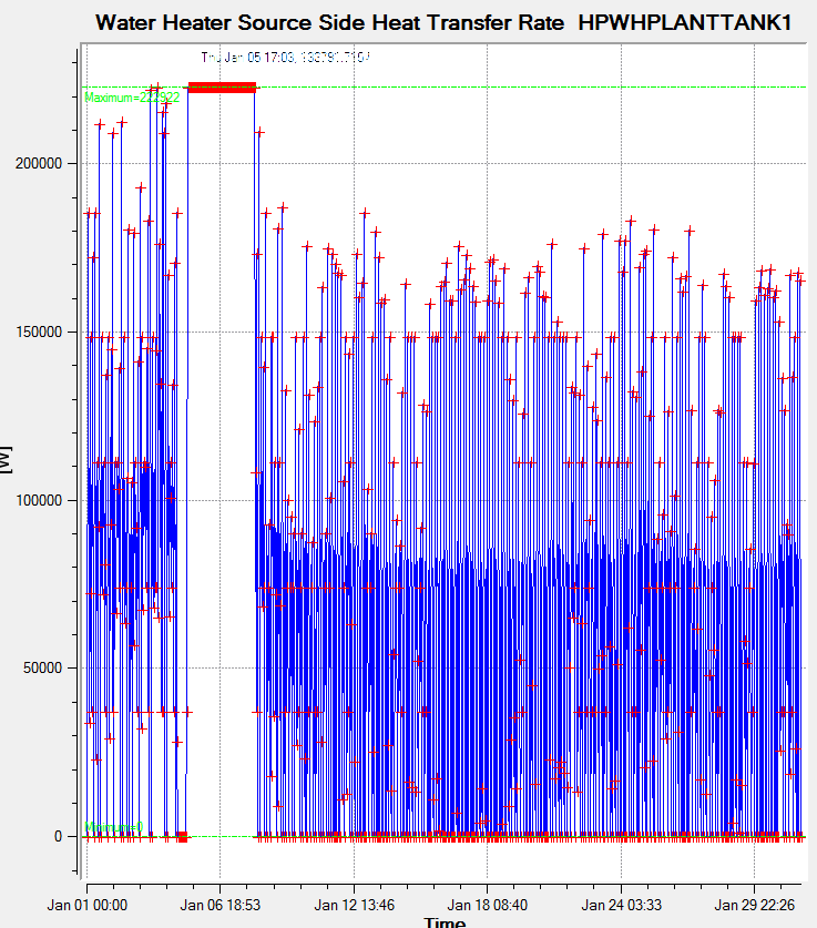
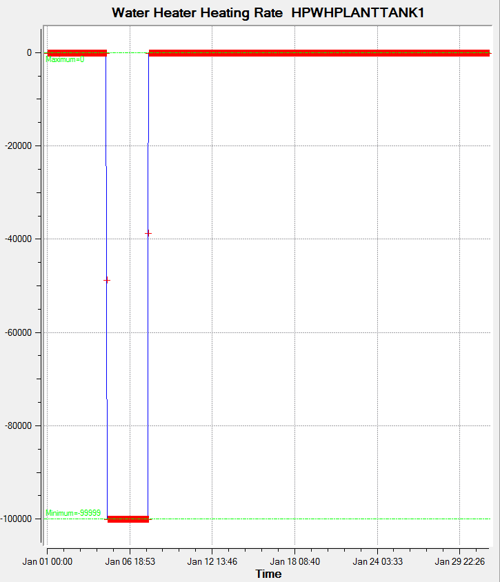
The weirdest thing is the temperature rises above -5C.water heater that the heat pump is connected to is heating at negative rate!
Has anyone experience such problem? Anything I can do about it?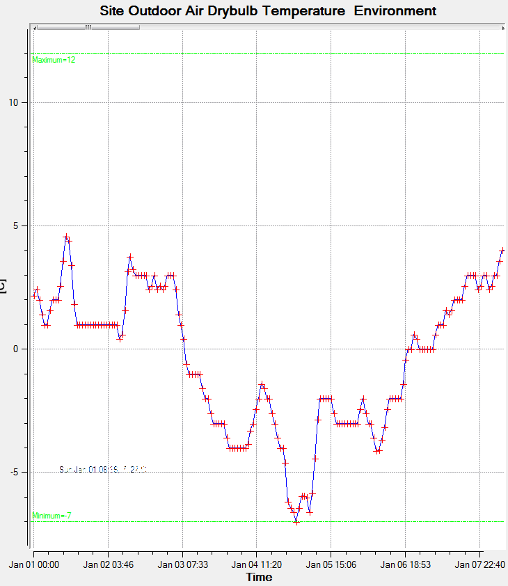 (/upfiles/14973424773713121.png)
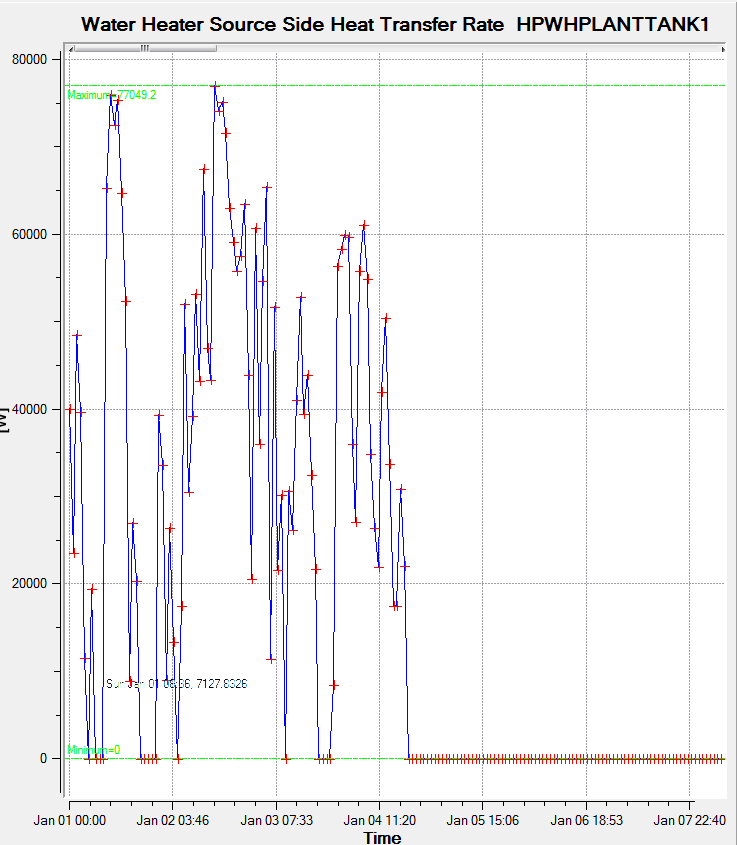
I discover a little more about what is happening. After the heat pump shut down, the water tank is actually drawing heating from the conditioned zones! The heating rate of coils become negative afterwards.
I have placed one of the heat pump code in below.
WaterHeater:HeatPump:PumpedCondenser,
WHPH1,                   !- Name
HVACTemplate-Always 1,   !- Availability Schedule Name
Always 55,   44.5,             !- Compressor Setpoint Temperature Schedule Name
5,   1.2,                     !- Dead Band Temperature Difference {deltaC}
WHPH1 LoadSide Inlet Node,  !- Condenser Water Inlet Node Name
WHPH1 LoadSide Outlet Node,  !- Condenser Water Outlet Node Name
autocalculate,           !- Condenser Water Flow Rate {m3/s}
autocalculate,           !- Evaporator Air Flow Rate {m3/s}
OutdoorAirOnly,          !- Inlet Air Configuration
,                        !- Air Inlet Node Name
,                        !- Air Outlet Node Name
HPPlantAirInletNode1,    !- Outdoor Air Node Name
HPPlantAirOutletNode1,   !- Exhaust Air Node Name
,                        !- Inlet Air Temperature Schedule Name
,                        !- Inlet Air Humidity Schedule Name
,                        !- Inlet Air Zone Name
WaterHeater:Mixed,       !- Tank Object Type
HPWHPlantTank1,          !- Tank Name
HPWH Use Inlet Node1,    !- Tank Use Side Inlet Node Name
HPWH Use Outlet Node1,   !- Tank Use Side Outlet Node Name
Coil:WaterHeating:AirToWaterHeatPump:Pumped,  !- DX Coil Object Type
HPWHPlantDXCoil1,        !- DX Coil Name
-5,                      !- Minimum Inlet Air Temperature for Compressor Operation {C}
,   26,                      !- Maximum Inlet Air Temperature for Compressor Operation {C}
Outdoors,                !- Compressor Location
HP Outdoor Temp, ,                        !- Compressor Ambient Temperature Schedule Name
Fan:OnOff,               !- Fan Object Type
HPWHPlantFan1,           !- Fan Name
BlowThrough,             !- Fan Placement
,                        !- On Cycle Parasitic Electric Load {W}
,                        !- Off Cycle Parasitic Electric Load {W}
, ;                        !- Parasitic Heat Rejection Location
,                        !- Inlet Air Mixer Node Name
,                        !- Outlet Air Splitter Node Name
,                        !- Inlet Air Mixer Schedule Name
Simultaneous;            !- Tank Element Control Logic


WaterHeater:Mixed,
HPWHPlantTank1,          !- Name
0, autosize,                !- Tank Volume {m3}
Always 38.3,             !- Setpoint Temperature Schedule Name
2,                       !- Deadband Temperature Difference {deltaC}
60,                      !- Maximum Temperature Limit {C}
Cycle,                   !- Heater Control Type
100000, autosize,                !- Heater Maximum Capacity {W}
0,                       !- Heater Minimum Capacity {W}
,                        !- Heater Ignition Minimum Flow Rate {m3/s}
,                        !- Heater Ignition Delay {s}
NaturalGas,              !- Heater Fuel Type
0.98,                    !- Heater Thermal Efficiency
,                        !- Part Load Factor Curve Name
,                        !- Off Cycle Parasitic Fuel Consumption Rate {W}
,                        !- Off Cycle Parasitic Fuel Type
,                        !- Off Cycle Parasitic Heat Fraction to Tank
,                        !- On Cycle Parasitic Fuel Consumption Rate {W}
,                        !- On Cycle Parasitic Fuel Type
,                        !- On Cycle Parasitic Heat Fraction to Tank
Outdoors,                !- Ambient Temperature Indicator
,                        !- Ambient Temperature Schedule Name
,                        !- Ambient Temperature Zone Name
HPWHPlantTank OA Node,   !- Ambient Temperature Outdoor Air Node Name
0,                       !- Off Cycle Loss Coefficient to Ambient Temperature {W/K}
0,                       !- Off Cycle Loss Fraction to Zone
0,                       !- On Cycle Loss Coefficient to Ambient Temperature {W/K}
0,                       !- On Cycle Loss Fraction to Zone
,                        !- Peak Use Flow Rate {m3/s}
,                        !- Use Flow Rate Fraction Schedule Name
,                        !- Cold Water Supply Temperature Schedule Name
HPWH Use Inlet Node1,    !- Use Side Inlet Node Name
HPWH Use Outlet Node1,   !- Use Side Outlet Node Name
1,                       !- Use Side Effectiveness
WHPH1 LoadSide Outlet Node,  !- Source Side Inlet Node Name
WHPH1 LoadSide Inlet Node,  !- Source Side Outlet Node Name
1,                       !- Source Side Effectiveness
autosize,                !- Use Side Design Flow Rate {m3/s}
autosize,                !- Source Side Design Flow Rate {m3/s}
1.5; 1.5,                     !- Indirect Water Heating Recovery Time {hr}
;             !- Source Side Flow Control Mode


Coil:WaterHeating:AirToWaterHeatPump:Pumped,
HPWHPlantDXCoil1,        !- Name
100000, 222922,                  !- Rated Heating Capacity {W}
2.363,                   !- Rated COP {W/W}
0.736,                   !- Rated Sensible Heat Ratio
19.7, 8.3,                     !- Rated Evaporator Inlet Air Dry-Bulb Temperature {C}
13.5, 6.1,                     !- Rated Evaporator Inlet Air Wet-Bulb Temperature {C}
38.8,                    !- Rated Condenser Inlet Water Temperature {C}
autocalculate,           !- Rated Evaporator Air Flow Rate {m3/s}
autocalculate,           !- Rated Condenser Water Flow Rate {m3/s}
Yes,                     !- Evaporator Fan Power Included in Rated COP
No,                      !- Condenser Pump Power Included in Rated COP
No,                      !- Condenser Pump Heat Included in Rated Heating Capacity and Rated COP
0,                       !- Condenser Water Pump Power {W}
0.1,                     !- Fraction of Condenser Pump Heat to Water
HPPlantFanAirOutletNode1,!- Evaporator Air Inlet Node Name
HPPlantAirOutletNode1,   !- Evaporator Air Outlet Node Name
WHPH1 LoadSide Inlet Node,  !- Condenser Water Inlet Node Name
WHPH1 LoadSide Outlet Node,  !- Condenser Water Outlet Node Name
100,                     !- Crankcase Heater Capacity {W}
5,                       !- Maximum Ambient Temperature for Crankcase Heater Operation {C}
WetBulbTemperature;      !- Evaporator Air Temperature Type for Curve Objects
 (/upfiles/14973424773713121.png)


