Question-and-Answer Resource for the Building Energy Modeling Community
Get started with the Help page
Ask Your Question

Revision history [back]

How to model a heatexchanger inside an airflownetwork?

In the example file of the MultiZone_SmallOffice_HeatRecoveryHXSL I would expect an Airflownetwork:Distribution:Component:HeatExchanger that is linked to the HeatExchanger:AirToAir:SensibleAndLatent. When I add the component myself and allocate it to an Airflownetwork:Distribution:Linkage (between the outside air node and the OA System node?) I don't get any errors. However flows don't add up. Is my linkage incorrect? For me the text from the IO manual is not clear. Does anyone have an example file with a working Airflownetwork:Distribution:Component:HeatExchanger or can anyone point me in the right direction? I want to model a system like the one below including heat exchanger inside the AirflowNetwork model.
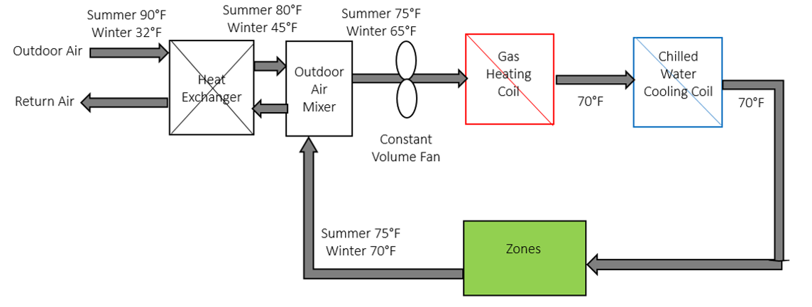
image description

From the IO reference: When a heat exchanger is used in an exhaust air energy recovery system (i.e., in an AirLoopHVAC:OutdoorAirSystem object to recover waste heat from exhaust air to pretreat incoming outdoor ventilation air), the heat exchanger is treated as a single component. The AirflowNetwork model only connects the two nodes associated with the incoming outdoor ventilation air, while the two exhaust nodes are not defined as part of the AirflowNetwork model. Therefore, each heat exchanger component used in an exhaust air energy recovery system has only one linkage object, similar to AirflowNetwork coil components.

How to model a heatexchanger inside an airflownetwork?

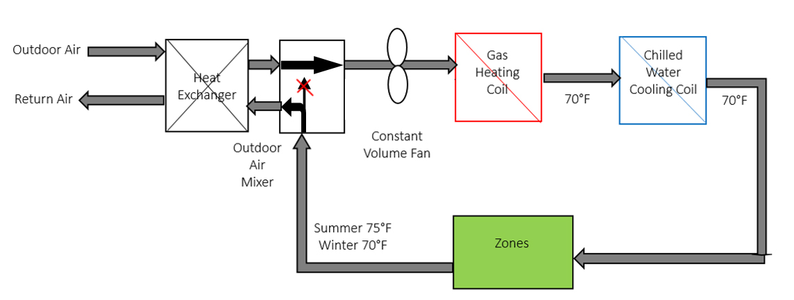
In the example file of the MultiZone_SmallOffice_HeatRecoveryHXSL I would expect an Airflownetwork:Distribution:Component:HeatExchanger that is linked to the HeatExchanger:AirToAir:SensibleAndLatent. When I add the component myself and allocate it to an Airflownetwork:Distribution:Linkage (between the outside air node and the OA System node?) I don't get any errors. However flows don't add up. Is my linkage incorrect? For me the text from the IO manual is not clear. Does anyone have an example file with a working Airflownetwork:Distribution:Component:HeatExchanger or can anyone point me in the right direction? I want to model a system like the one below including heat exchanger inside the AirflowNetwork model.model (flow to fan = 100% outdoor air in OA Mixer).

image descriptionimage description

From the IO reference: When a heat exchanger is used in an exhaust air energy recovery system (i.e., in an AirLoopHVAC:OutdoorAirSystem object to recover waste heat from exhaust air to pretreat incoming outdoor ventilation air), the heat exchanger is treated as a single component. The AirflowNetwork model only connects the two nodes associated with the incoming outdoor ventilation air, while the two exhaust nodes are not defined as part of the AirflowNetwork model. Therefore, each heat exchanger component used in an exhaust air energy recovery system has only one linkage object, similar to AirflowNetwork coil components.

How to model a heatexchanger inside an airflownetwork?

In the example file of the MultiZone_SmallOffice_HeatRecoveryHXSL I would expect an Airflownetwork:Distribution:Component:HeatExchanger that is linked to the HeatExchanger:AirToAir:SensibleAndLatent. When I add the component myself and allocate it to an Airflownetwork:Distribution:Linkage (between the outside air node and the OA System node?) I don't get any errors. However flows don't add up. Is my linkage incorrect? For me the text from the IO manual is not clear. Does anyone have an example file with a working Airflownetwork:Distribution:Component:HeatExchanger or can anyone point me in the right direction? I want to model a system like the one below including heat exchanger inside the AirflowNetwork model (flow to fan = 100% outdoor air in OA Mixer).

image description

From the IO reference: When a heat exchanger is used in an exhaust air energy recovery system (i.e., in an AirLoopHVAC:OutdoorAirSystem object to recover waste heat from exhaust air to pretreat incoming outdoor ventilation air), the heat exchanger is treated as a single component. The AirflowNetwork model only connects the two nodes associated with the incoming outdoor ventilation air, while the two exhaust nodes are not defined as part of the AirflowNetwork model. Therefore, each heat exchanger component used in an exhaust air energy recovery system has only one linkage object, similar to AirflowNetwork coil components.
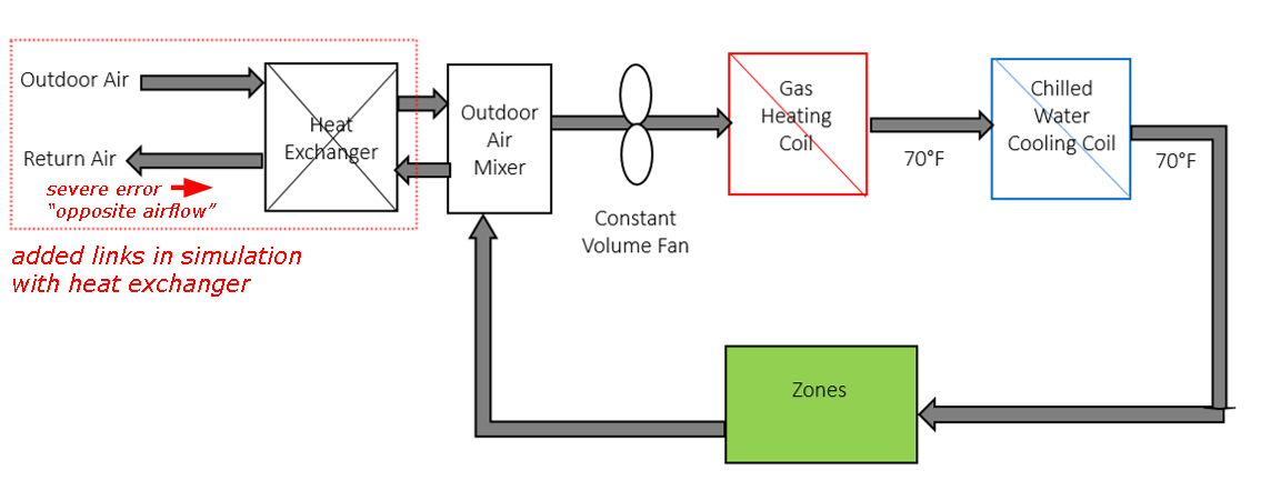
Update: I managed to solve the imbalance. Apparently a return node was turned off in the airloop and this interfered with the AFN calculation. However I still have a problem. When I model the system without the exchanger all flows are OK, but when I model the system with the Airflownetwork:Distribution:Component:HeatExchanger E+ gives me a severe error: "The airflow direction is opposite to the intended direction (from node 1 to node 2) in AirflowNetwork:Distribution:Linkage = RELIEFLLINK2" I don't get this. The AFN solver has to solve almost exactly the same network. I only have two extra links to be able to include the exchanger. Why would this turn around the flow direction? (red arrow) image description

How to model a heatexchanger inside an airflownetwork?

In the example file of the MultiZone_SmallOffice_HeatRecoveryHXSL I would expect an Airflownetwork:Distribution:Component:HeatExchanger that is linked to the HeatExchanger:AirToAir:SensibleAndLatent. When I add the component myself and allocate it to an Airflownetwork:Distribution:Linkage (between the outside air node and the OA System node?) I don't get any errors. However flows don't add up. Is my linkage incorrect? For me the text from the IO manual is not clear. Does anyone have an example file with a working Airflownetwork:Distribution:Component:HeatExchanger or can anyone point me in the right direction? I want to model a system like the one below including heat exchanger inside the AirflowNetwork model (flow to fan = 100% outdoor air in OA Mixer).

image description

From the IO reference: When a heat exchanger is used in an exhaust air energy recovery system (i.e., in an AirLoopHVAC:OutdoorAirSystem object to recover waste heat from exhaust air to pretreat incoming outdoor ventilation air), the heat exchanger is treated as a single component. The AirflowNetwork model only connects the two nodes associated with the incoming outdoor ventilation air, while the two exhaust nodes are not defined as part of the AirflowNetwork model. Therefore, each heat exchanger component used in an exhaust air energy recovery system has only one linkage object, similar to AirflowNetwork coil components.
Update: I managed to solve the imbalance. Apparently a return node was turned off in the airloop and this interfered with the AFN calculation. However I still have a problem. When I model the system without the exchanger all flows are OK, but when I model the system with the Airflownetwork:Distribution:Component:HeatExchanger E+ gives me a severe error: "The airflow direction is opposite to the intended direction (from node 1 to node 2) in AirflowNetwork:Distribution:Linkage = RELIEFLLINK2" I don't get this. The AFN solver has to solve almost exactly +-exactly the same network. I only have two extra links to be able to include the exchanger. Why would this turn around the flow direction? (red arrow) image description

How to model a heatexchanger inside an airflownetwork?

In the example file of the MultiZone_SmallOffice_HeatRecoveryHXSL I would expect an Airflownetwork:Distribution:Component:HeatExchanger that is linked to the HeatExchanger:AirToAir:SensibleAndLatent. When I add the component myself and allocate it to an Airflownetwork:Distribution:Linkage (between the outside air node and the OA System node?) I don't get any errors. However flows don't add up. Is my linkage incorrect? For me the text from the IO manual is not clear. Does anyone have an example file with a working Airflownetwork:Distribution:Component:HeatExchanger or can anyone point me in the right direction? I want to model a system like the one below including heat exchanger inside the AirflowNetwork model (flow to fan = 100% outdoor air in OA Mixer).

image description

From the IO reference: When a heat exchanger is used in an exhaust air energy recovery system (i.e., in an AirLoopHVAC:OutdoorAirSystem object to recover waste heat from exhaust air to pretreat incoming outdoor ventilation air), the heat exchanger is treated as a single component. The AirflowNetwork model only connects the two nodes associated with the incoming outdoor ventilation air, while the two exhaust nodes are not defined as part of the AirflowNetwork model. Therefore, each heat exchanger component used in an exhaust air energy recovery system has only one linkage object, similar to AirflowNetwork coil components.
Update: I managed to solve the imbalance. Apparently a return node was turned off in the airloop and this interfered with the AFN calculation. However I still have a problem. When I model the system without the exchanger all flows are OK, but when I model the system with the Airflownetwork:Distribution:Component:HeatExchanger E+ gives me a severe error: "The airflow direction is opposite to the intended direction (from node 1 to node 2) in AirflowNetwork:Distribution:Linkage = RELIEFLLINK2" I don't get this. The AFN solver has to solve +-exactly the same network. I only have two extra links to be able to include the exchanger. Why would this turn around the flow direction? (red arrow) image description

image description

How to model a heatexchanger inside an airflownetwork?

In the example file of the MultiZone_SmallOffice_HeatRecoveryHXSL I would expect an Airflownetwork:Distribution:Component:HeatExchanger that is linked to the HeatExchanger:AirToAir:SensibleAndLatent. When I add the component myself and allocate it to an Airflownetwork:Distribution:Linkage (between the outside air node and the OA System node?) I don't get any errors. However flows don't add up. Is my linkage incorrect? For me the text from the IO manual is not clear. Does anyone have an example file with a working Airflownetwork:Distribution:Component:HeatExchanger or can anyone point me in the right direction? I want to model a system like the one below including heat exchanger inside the AirflowNetwork model (flow to fan = 100% outdoor air in OA Mixer).

image description

From the IO reference: When a heat exchanger is used in an exhaust air energy recovery system (i.e., in an AirLoopHVAC:OutdoorAirSystem object to recover waste heat from exhaust air to pretreat incoming outdoor ventilation air), the heat exchanger is treated as a single component. The AirflowNetwork model only connects the two nodes associated with the incoming outdoor ventilation air, while the two exhaust nodes are not defined as part of the AirflowNetwork model. Therefore, each heat exchanger component used in an exhaust air energy recovery system has only one linkage object, similar to AirflowNetwork coil components.
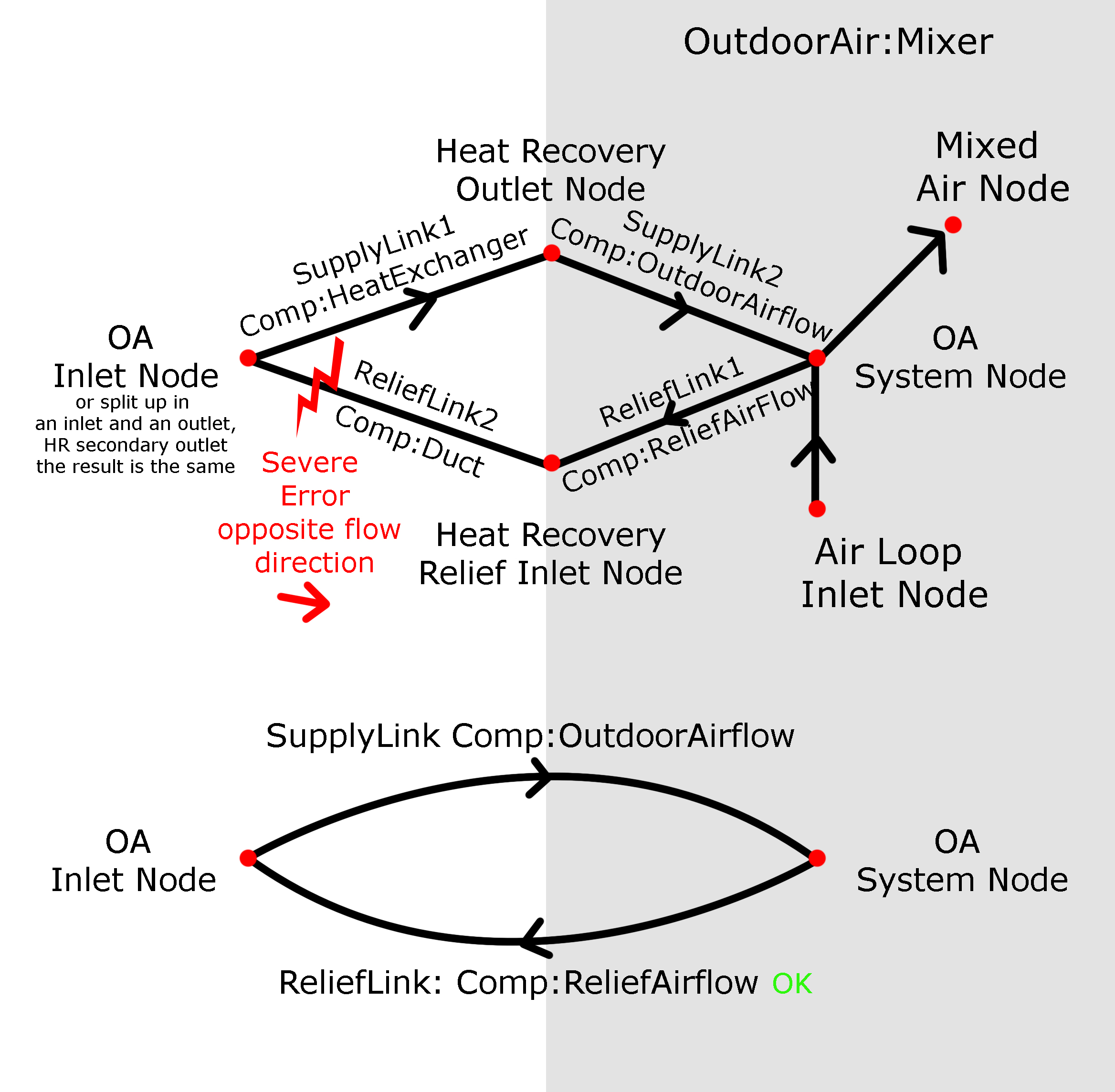
Update: I managed to solve the imbalance. Apparently a return node was turned off in the airloop and this interfered with the AFN calculation. However I still have a problem. When I model the system without the exchanger all flows are OK, but when I model the system with the Airflownetwork:Distribution:Component:HeatExchanger E+ gives me a severe error: "The airflow direction is opposite to the intended direction (from node 1 to node 2) in AirflowNetwork:Distribution:Linkage = RELIEFLLINK2" I don't get this. The AFN solver has to solve +-exactly the same network. I only have two extra links to be able to include the exchanger. Why would this turn around the flow direction? (red arrow) image description image description image description

image description

How to model a heatexchanger inside an airflownetwork?

In the example file of the MultiZone_SmallOffice_HeatRecoveryHXSL I would expect an Airflownetwork:Distribution:Component:HeatExchanger that is linked to the HeatExchanger:AirToAir:SensibleAndLatent. When I add the component myself and allocate it to an Airflownetwork:Distribution:Linkage (between the outside air node and the OA System node?) I don't get any errors. However flows don't add up. Is my linkage incorrect? For me the text from the IO manual is not clear. Does anyone have an example file with a working Airflownetwork:Distribution:Component:HeatExchanger or can anyone point me in the right direction? I want to model a system like the one below including heat exchanger inside the AirflowNetwork model (flow to fan = 100% outdoor air in OA Mixer).

image description

From the IO reference: When a heat exchanger is used in an exhaust air energy recovery system (i.e., in an AirLoopHVAC:OutdoorAirSystem object to recover waste heat from exhaust air to pretreat incoming outdoor ventilation air), the heat exchanger is treated as a single component. The AirflowNetwork model only connects the two nodes associated with the incoming outdoor ventilation air, while the two exhaust nodes are not defined as part of the AirflowNetwork model. Therefore, each heat exchanger component used in an exhaust air energy recovery system has only one linkage object, similar to AirflowNetwork coil components.

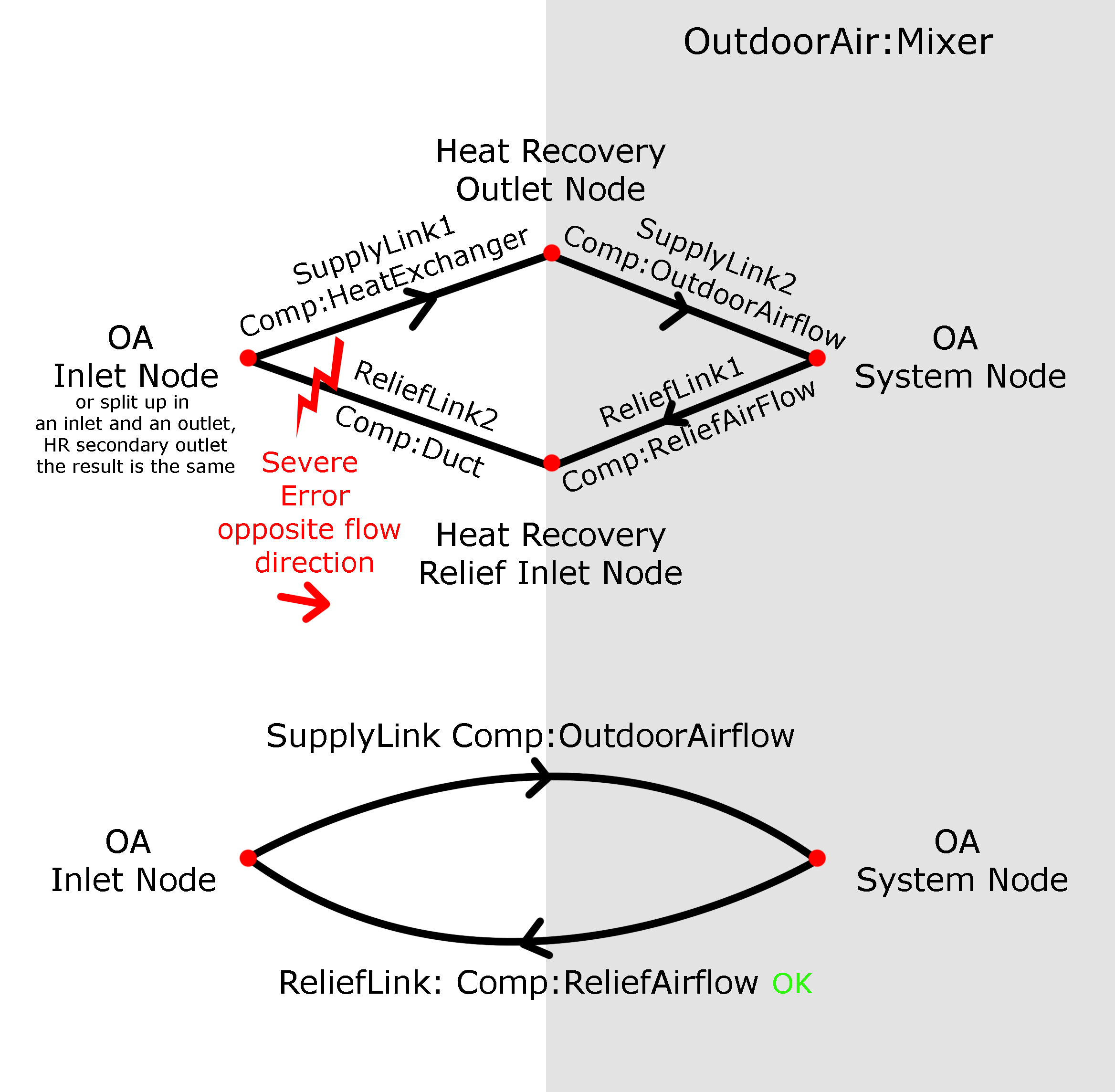
Update: I managed to solve the imbalance. Apparently a return node was turned off in the airloop and this interfered with the AFN calculation. However I still have a problem. When I model the system without the exchanger all flows are OK, but when I model the system with the Airflownetwork:Distribution:Component:HeatExchanger E+ gives me a severe error: "The airflow direction is opposite to the intended direction (from node 1 to node 2) in AirflowNetwork:Distribution:Linkage = RELIEFLLINK2" I don't get this. The AFN solver has to solve +-exactly the same network. I only have two extra links to be able to include the exchanger. Why would this turn around the flow direction? (red arrow) image description image description image description