Differences between VAV:Reheat and VAV:HeatAndCool:Reheat

I gave it the exact same title as this old post. It seems that AirTerminal:SingleDuct:VAV:Reheat and AirTerminal:SingleDuct:VAV:HeatAndCool:Reheat have not changed that much since 8 years ago, but I'm not satisfied with the answer in the old post. To be more precise, I want to clarify the difference between AirTerminal:SingleDuct:VAV:Reheat with Reverse damper heating action and AirTerminal:SingleDuct:VAV:HeatAndCool:Reheat.
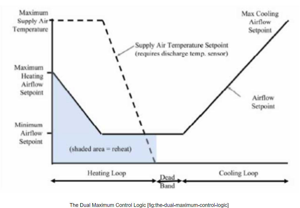
For AirTerminal:SingleDuct:VAV:Reheat, the Reverse damper heating action is also called the dual maximum control logic as illustrated in the following figure.
For AirTerminal:SingleDuct:VAV:HeatAndCool:Reheat, Adam Hilton, the questioner of the old post interpreted Input/Output Reference as follows:
VAV:HeatAndCool:Reheatincreases the air flow to maximum first, then modulates the reheat valve to 100%.
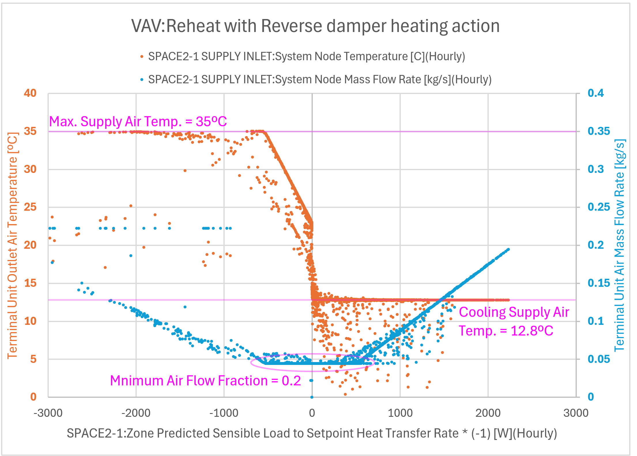
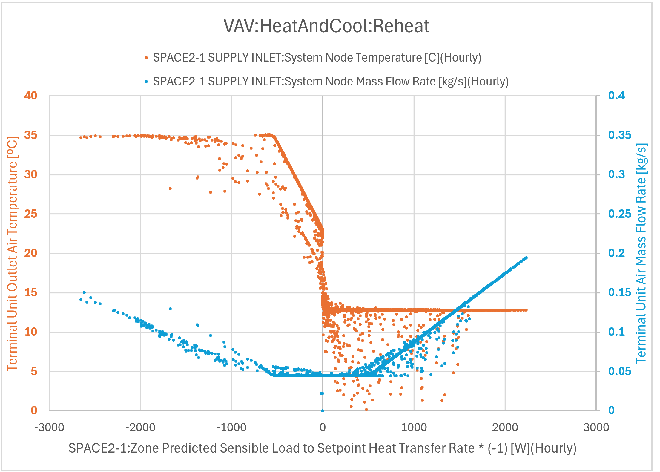
This is incorrect, at least according to simulation results. When the heating load is small enough to handle with the Mnimum Air Flow Fraction, the airflow starts from the Mnimum Air Flow Fraction, and the supply air temperature is gradually increased. The aiflow increases only after the heating load increases and the supply air temperature reaches the Maximum Reheat Air Temperature, which is the same as the figure above! If this simulation result is not as intended for AirTerminal:SingleDuct:VAV:HeatAndCool:Reheat, this should be a bug.
I don't know the difference between AirTerminal:SingleDuct:VAV:Reheat with Reverse damper heating action and AirTerminal:SingleDuct:VAV:HeatAndCool:Reheat. Both have Mnimum Air Flow Fraction and Maximum Reheat Air Temperature. When the heating load increases, both start with Mnimum Air Flow Fraction and both increase airflow after the supply air temperature reaches Maximum Reheat Air Temperature.
Actually, the simulation results of AirTerminal:SingleDuct:VAV:Reheat with Reverse damper heating action and AirTerminal:SingleDuct:VAV:HeatAndCool:Reheatare not exactly the same, but their control logic looks very similar.
Could someone clarify the difference between AirTerminal:SingleDuct:VAV:Reheat with Reverse damper heating action and AirTerminal:SingleDuct:VAV:HeatAndCool:Reheat? I would appreciate it even more if you could illustrate it. The problem is that Input/Output Reference does not illustrate the control logic of AirTerminal:SingleDuct:VAV:HeatAndCool:Reheat.
UPDATE
I plotted simulation results as shown below according to @rraustad 's advice. The models are baesd on the ExampleFile HVACTemplate-5ZoneVAVWaterCooled.idf. The figures appear to be similar, but the model with AirTerminal:SingleDuct:VAV:HeatAndCool:Reheat has less outliners, 3% less annual heating energy (51.9GJ vs 53.7GJ) and 50% less unmet hours (66h vs 127h) compared to the model with AirTerminal:SingleDuct:VAV:Reheat with Reverse damper heating action. I'm going to use AirTerminal:SingleDuct:VAV:HeatAndCool:Reheat to model variable heating airflow.
I overlooked an important difference between VAV:Reheat and VAV:HeatAndCool:Reheat. AirTerminal:SingleDuct:VAV:HeatAndCool:Reheat does not have an input field for Design Specification Outdoor Air Object Name. It cannot supply stable OA flow. It turned out to be useless.


@rraustad I would be grateful for your advice.
So according to the above plots the HeatAndCool terminal unit is not responding as originally intended. Given the 2 independent variables, air flow rate and coil capacity, the air side damper fraction and the coil capacity fraction would have to be linked together. I think the first thing needed is to look for CBVAV sequence of operations documents. If not found then some consensus on how CBVAV terminal units should respond to heating loads. If I recall correctly, CBVAV supply temperature is set to keep the maximum damper position in one of zones at 1.
Engineering Reference:
@rraustad You are correct.
VAV:Reheatwith reverse damper heating action andVAV:HeatAndCool:Reheathave different control logic. And in detail, both controls may differ slightly from the common VAV control logic for heating in my region:@rraustad Anyway, the simulation result is the most important, and
AirTerminal:SingleDuct:VAV:HeatAndCool:Reheatseems to work closer to what I expect. Thanks again for your advice.