Question-and-Answer Resource for the Building Energy Modeling Community
Get started with the Help page
Ask Your Question
2

Modelling fluid to fluid heat exchanger with more inlet and outlet nodes

asked 2015-07-13 08:08:11 -0500

Waseem's avatar

updated 2015-07-16 10:39:18 -0500

I am modelling an HVAC system that has the below configuration; 
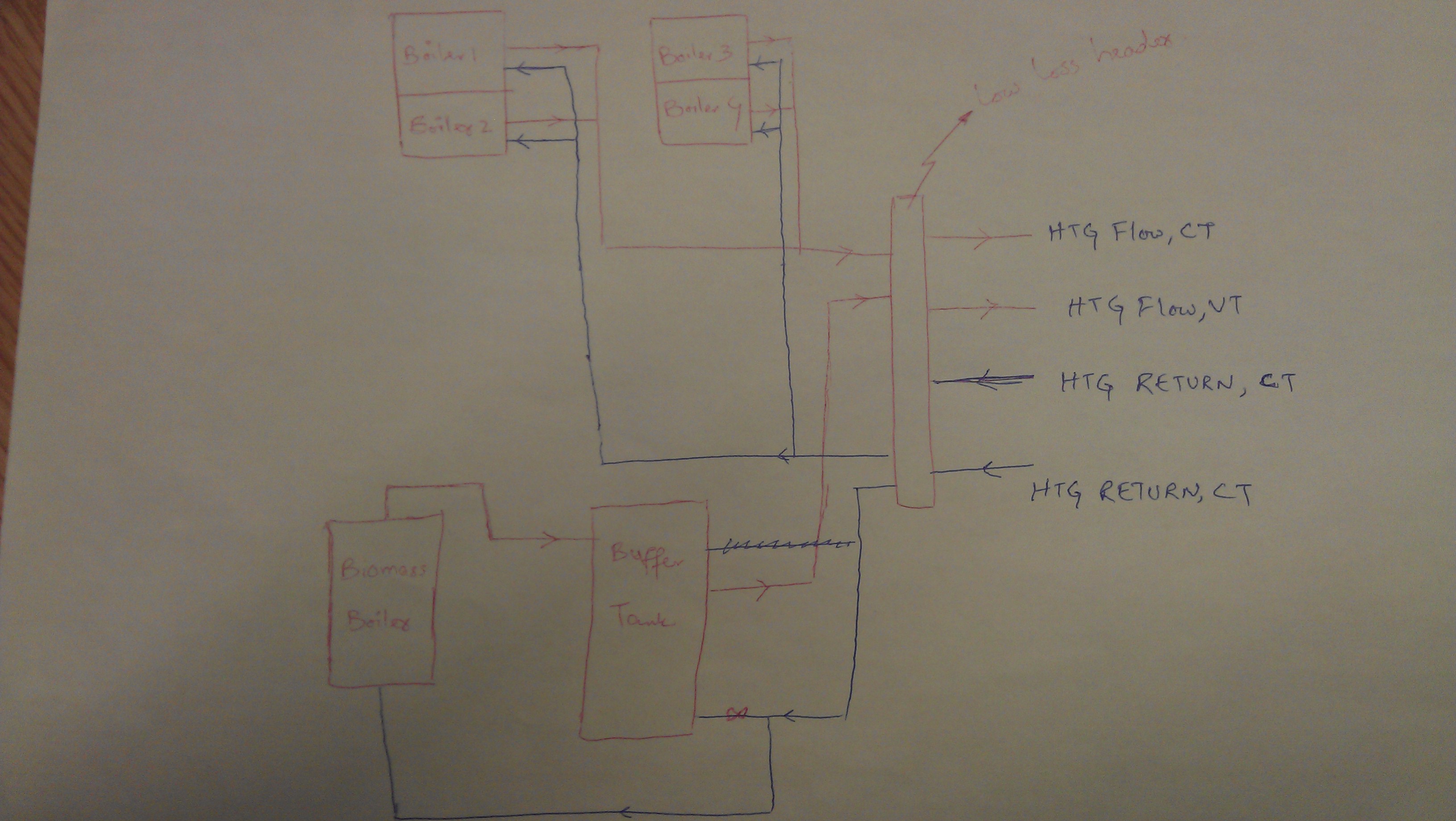
one of the boilers (biomass) heats up the buffer tank and the other four boilers (gas boilers) uses a low loss header to heat up the tank. I assume I can model low loss header by using HeatExchanger:FluidToFluid, am I right?

But the problem is I have many input and output nodes (more than I can input in the EnergyPlus HeatExchanger:FluidToFluid object. Any ideas how to model this system in EnergyPlus?

I think the use of splitters/mixers won't help, because the low loss headers has output nodes for variable temperature circuit (i.e. serving radiant panels), constant temperature circuit (services hot water to AHUs, underfloor heating) and connections going back to buffer vessels. Any ideas on this?

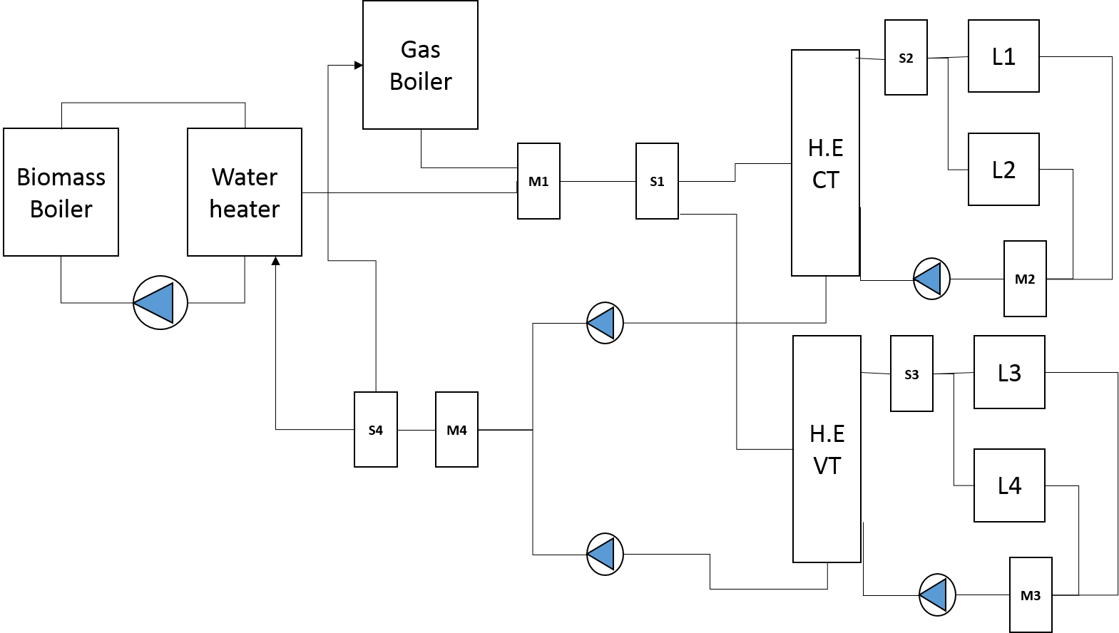
Also, how once can model variable temperature and constant temperature circuits? Do I have to use set-point managers or something else? Or we can simplify the HVAC system for modelling purposes? I have added a second picture to show EnergyPlus loops. HVAC system

EnergyPlus layout

edit retag flag offensive close merge delete

Comments

@Waseem I removed some of your tags that were very specific and not likely to be used.

MatthewSteen's avatar MatthewSteen  ( 2015-07-16 10:40:26 -0500 )edit
Waseem's avatar Waseem  ( 2015-07-16 13:37:34 -0500 )edit

@Waseem: I'm curious what you program you used to draw the computer schematic?

Julien Marrec's avatar Julien Marrec  ( 2016-02-02 04:49:34 -0500 )edit

@Julien Marrec: I think it was Microsoft Powerpoint.

Waseem's avatar Waseem  ( 2016-02-02 07:10:39 -0500 )edit

1 Answer

Sort by ยป oldest newest most voted
6

answered 2015-07-13 12:18:28 -0500

kwalkerman's avatar

Hi Waseem,

I think it'll help if you think about the solution if you draw the above schematic including the EnergyPlus loops. I would start with:

  1. Put the biomass boiler on the supply side of a loop ("Biomass Loop")
  2. Your "Buffer Tank" should be a "WaterHeater:Mixed" or "WaterHeater:Stratified" object. It's source nodes should be on the demand side of "Biomass Loop" and the use side nodes should be on the supply side of "HW Loop"
  3. Your gas boilers could also be on the supply side of "HW Loop". Set the loop load distribution scheme to "Sequential" and put the gas boilers after the water heater in the PlantEquipmentList.

The above would operate as follows:

  • biomass boiler operates to maintain temperature in the water heater
  • when there is a load, the temperature in the water heater is drawn down
  • if the water heater gets too cold to satisfy the load, the gas boilers are called on
  • the gas boilers are never used to heat the water heater

If you want to use the gas boilers to heat the water heater directly, you'll have to get more creative.

edit flag offensive delete link more

Comments

Hi @kwalkerman, Thanks for the input, appreciated. I will give it a try and will update here. Hopefully will get feedback after implementing it :)

Waseem's avatar Waseem  ( 2015-07-13 12:41:42 -0500 )edit

@kwalkerman: You did not mention about the low loss header, can I model it using heat exchanger or there is no need of it? Also, what about differentiating CT and VT circuits, how to differentiate/divide that circuits?

Waseem's avatar Waseem  ( 2015-07-13 14:19:11 -0500 )edit

@Waseem - I don't think that there is a component in EnergyPlus that acts exactly like your low-loss header. In a way the "HW Loop" is acting most like your low-loss header. With energy modeling, think about where the energy comes from, where it goes, and how it gets there - and select the best modeling components to achieve those goals. They might be named something different from what your real-world component is named.

kwalkerman's avatar kwalkerman  ( 2015-07-13 15:15:30 -0500 )edit

Hi @kwalkerman: I drew the schematic for EnergyPlus loops as you suggested. Please see the question as I have attached second picture there. Is this how you were mentioning the system to be? I have used mixer and splitter, is this correct? also, there will be two pumps for the whole systems (one per each loop)? Can I use splitter after mixer to account for VT and CT then using Set-point managers or there is no need for that? Thanks again.

Waseem's avatar Waseem  ( 2015-07-14 11:21:33 -0500 )edit

@Waseem - that is pretty much what I was thinking, except that the pump for the HW Loop would be before the supply splitter!

The mixer and splitter you drew look like they are the supply-splitter and supply-mixer for the HW Loop. If there is more than one load on this loop, you will also have a demand-splitter and demand-mixer.

I'm not sure what you mean by "VT and CT" - please clarify.

Regarding SetpointManagers - there are many options and they are pretty flexible! You will need at least one for each Loop. You can use more than one, but this can result in strange operating behavior.

kwalkerman's avatar kwalkerman  ( 2015-07-14 13:15:05 -0500 )edit

Your Answer

Please start posting anonymously - your entry will be published after you log in or create a new account.

Add Answer

Careers

Question Tools

3 followers

Stats

Asked: 2015-07-13 08:08:11 -0500

Seen: 647 times

Last updated: Jul 16 '15