Question-and-Answer Resource for the Building Energy Modeling Community
Get started with the Help page
Ask Your Question
3

Model heat recovery with a dedicated heat pump between inlet and outlet AHU air flows [E+]

asked 2015-07-08 05:23:18 -0600

Gio's avatar

updated 2015-07-12 10:21:52 -0600

Good morning, I'm modeling a hvac system with a AHU. It is equipped with a heat recovery composed by a dedicated heat pump placed between the inlet and outlet air flows.

To better explain it, it's a invertible heat pump that during summer works with the evaporator in the inlet air flow and the condenser in the outlet; in winter the contrary.

The literal english translation of this system (from italian) is "active thermodynamic heat recovery", I don't know if this information could help.

I didn't find a component for this issue, is there anything? Otherwise, is there a way to model it?

Thanks to everybody!

edit retag flag offensive close merge delete

2 Answers

Sort by ยป oldest newest most voted
3

answered 2015-07-17 14:28:05 -0600

In EnergyPlus, the AirLoopHVAC:UnitaryHeatPump:AirToAir system is what you describe. This system serves multiple zones. If you are conditioning only one zone, use the ZoneHVAC:PackagedTerminalHeatPump. These systems use both a cooling and heating coil to model both modes of operation even though the real system has only one indoor coil. Look at the example file HeatPump.idf to see how the multizone air loop is configured, or look at PackagedTerminalHeatPump to see how the zone heat pump is configured.

edit flag offensive delete link more

Comments

Sorry Gio, I did not notice this comment until now. The HX in this figure assists the cooling coil. In E+ see HeatExchanger:Desiccant:BalancedFlow. Of course, this object is used for desiccant HXs, and I believe your application of for sensible only heat transfer. The next hurdle you will face is to be able to set up the coefficients in HeatExchanger:Desiccant:BalancedFlow:PerformanceDataType1 to provide the performance for your HX. If you can generate some inlet and outlet temperatures and humidity ratios, you can probably create the performance curve necessary to model this type of HX.

Gio's avatar Gio  ( 2015-11-20 03:49:53 -0600 )edit

I ran out of characters so continuing here... I would start by using an example file's input for the desiccant HX and review the results. Look at example file FurnaceWithDXSystem_CoolingHXAssisted. This model is not exactly like your schematic, the HX wraps around the cooling coil. I am not sure if you can configure these objects as you show. The other E+ object tor review is Dehumidifier:Desiccant:NoFans. You will also need to come up with coefficients for this object but to start, just try to configure as you show in the schematic.

Gio's avatar Gio  ( 2015-11-20 03:50:04 -0600 )edit

One more object to review. The Dehumidifier:Desicant:System. See DesiccantDehumidifierWithCompanionCoil example file.

Gio's avatar Gio  ( 2015-11-20 03:50:11 -0600 )edit
1

answered 2015-10-04 10:04:12 -0600

Gio's avatar

updated 2015-10-05 03:52:11 -0600

First of all, thanks a lot for your answer. Probably I understood wrong, but it doesn't seem what I wanted to model.

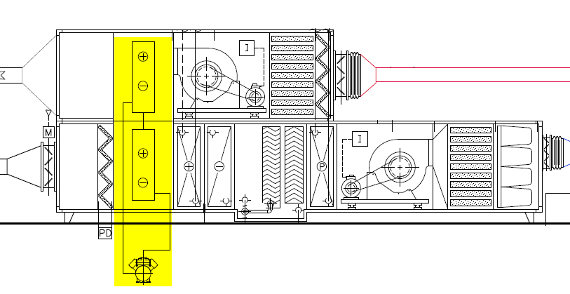
This system is placed within the AHU and serves multiple zones. This system is used in place of a heat recovery, between the outside air flow (coming into the AHU) and the exhaust air flow (going out from the AHU); it doesn't only recover heat but it is a heat pump air to air that works with very advantageous conditions. The problem is that it works in the AHU, not directly in the indoor zones.

image description

edit flag offensive delete link more

Comments

Can you explain what all the components in your AHU are not just the heat recovery part, this might help better understand what you are trying to model?

Annie Marston's avatar Annie Marston  ( 2015-10-04 15:19:05 -0600 )edit

Sure! I attached a scheme under my question... I hope it's enough to understand the operation of the system :)

Gio's avatar Gio  ( 2015-10-05 03:56:26 -0600 )edit

Sorry Gio, I did not notice this comment until now.

The HX in this figure assists the cooling coil. In E+ see HeatExchanger:Desiccant:BalancedFlow. Of course, this object is used for desiccant HXs, and I believe your application of for sensible only heat transfer. The next hurdle you will face is to be able to set up the coefficients in HeatExchanger:Desiccant:BalancedFlow:PerformanceDataType1 to provide the performance for your HX. If you can generate some inlet and outlet temperatures and humidity ratios, you can probably create the performance curve necessary to model this type of HX.

rraustad's avatar rraustad  ( 2015-11-13 07:14:25 -0600 )edit

I ran out of characters so continuing here...

I would start by using an example file's input for the desiccant HX and review the results. Look at example file FurnaceWithDXSystem_CoolingHXAssisted. This model is not exactly like your schematic, the HX wraps around the cooling coil. I am not sure if you can configure these objects as you show. The other E+ object tor review is Dehumidifier:Desiccant:NoFans. You will also need to come up with coefficients for this object but to start, just try to configure as you show in the schematic.

rraustad's avatar rraustad  ( 2015-11-13 07:22:19 -0600 )edit

One more object to review. The Dehumidifier:Desicant:System. See DesiccantDehumidifierWithCompanionCoil example file.

rraustad's avatar rraustad  ( 2015-11-13 07:56:14 -0600 )edit

Your Answer

Please start posting anonymously - your entry will be published after you log in or create a new account.

Add Answer

Training Workshops

Careers

Question Tools

1 follower

Stats

Asked: 2015-07-08 05:23:18 -0600

Seen: 466 times

Last updated: Oct 05 '15