Question-and-Answer Resource for the Building Energy Modeling Community
Get started with the Help page
Ask Your Question
4

Cooling coil sizing difference

asked 2021-10-02 09:51:13 -0500

obuchely's avatar

updated 2021-10-02 11:34:04 -0500

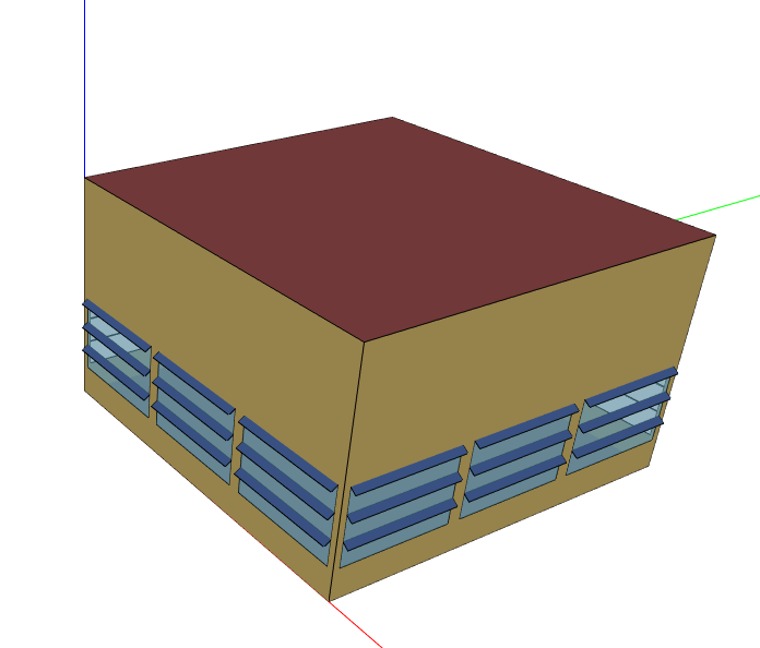
  1. I am doing a cooling load calculations and coil selection for a single zone project. image description
  2. DDY conditions were imported in the site tab.
  3. In simulation tab/ Simulation control/ Do HVAC simulation for sizing periods was and Run simulation for sizing periods is ON and Run simulation for weather file run periods is OFF.
  4. Cooling coil total cooling rate and Cooling coil sensible cooling rate were set to ON in the OUTPUT variables tab

Results:

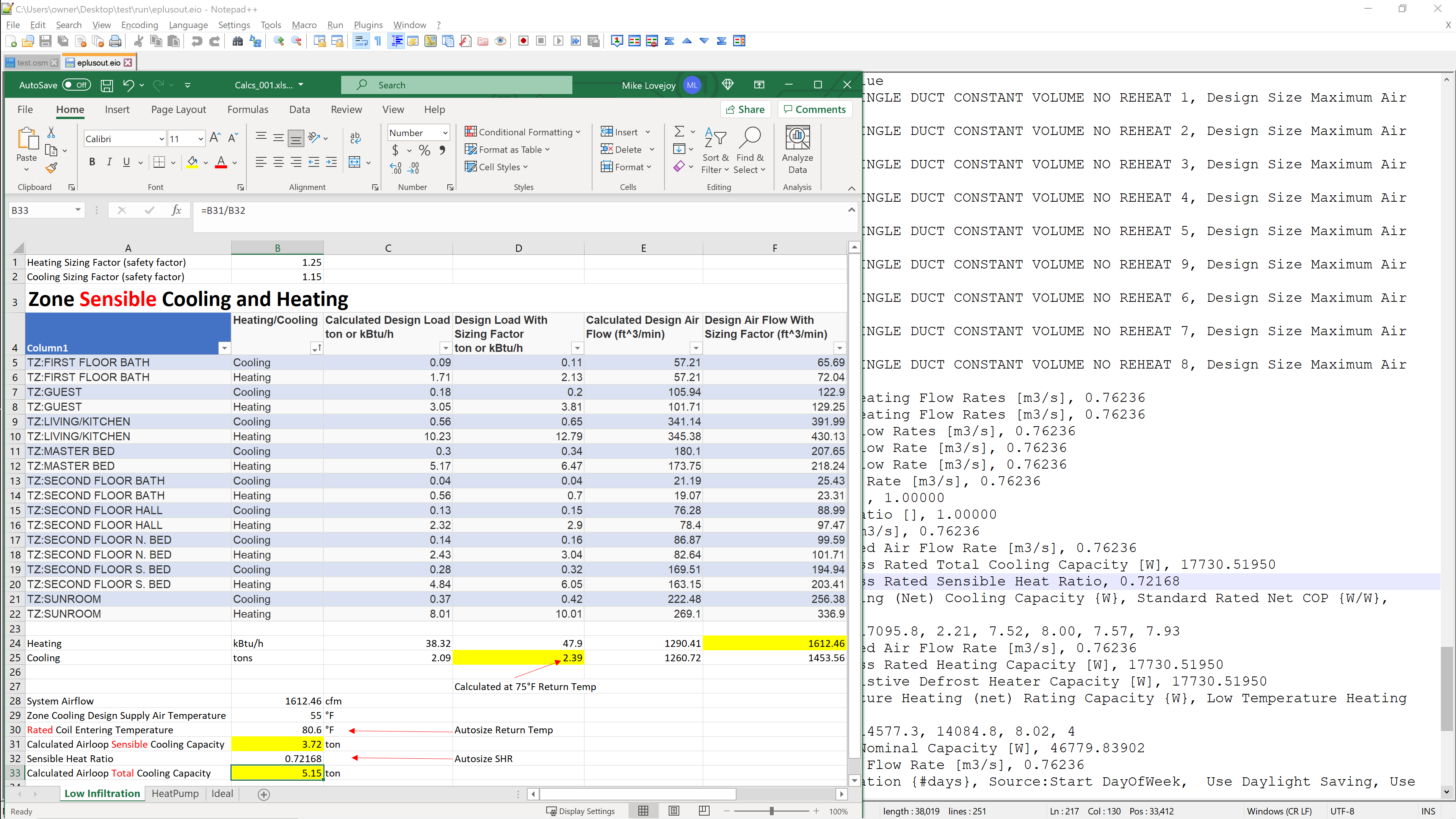
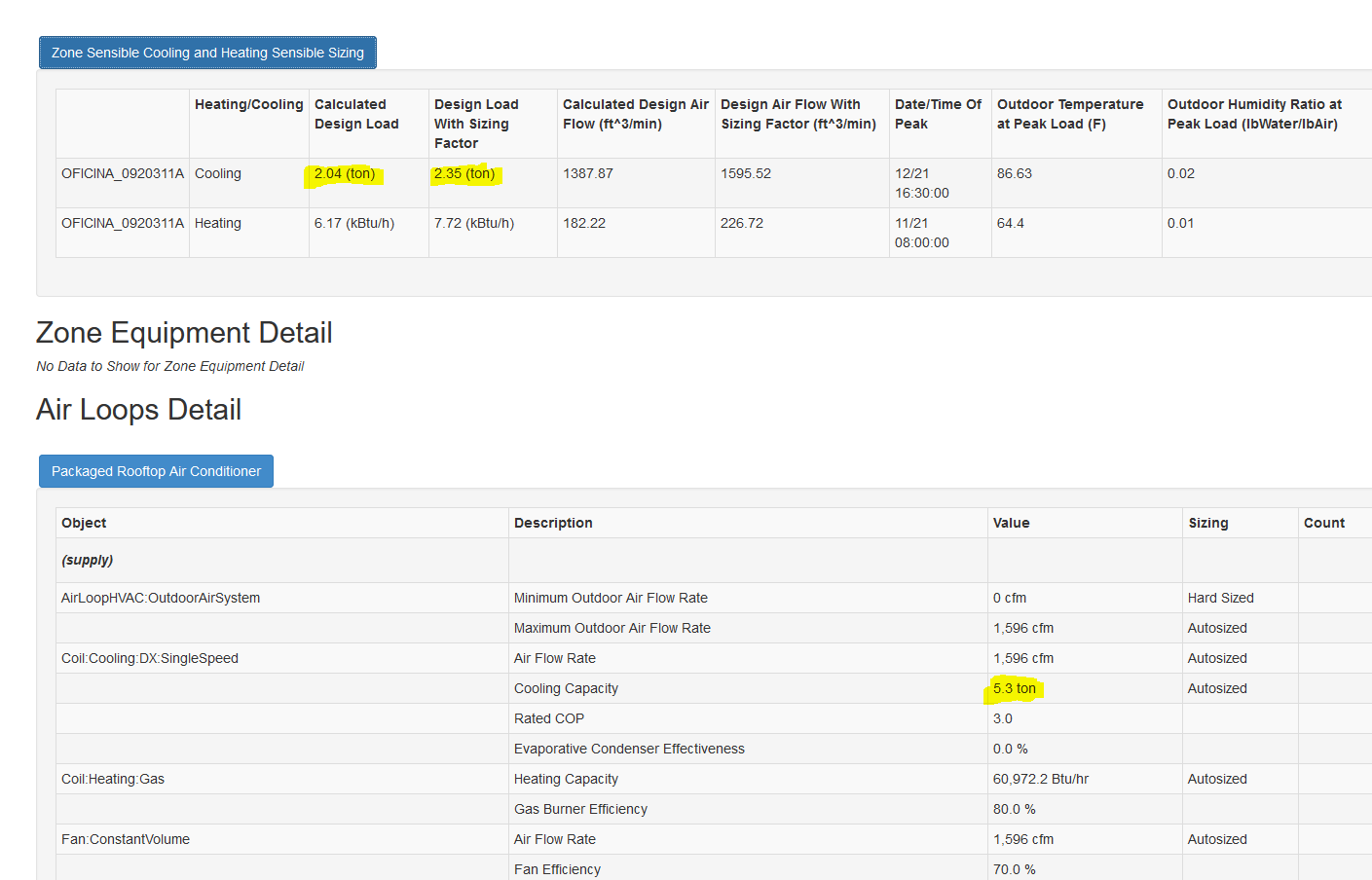
  1. In the Openstudio result: Zone sensible cooling and heating sensible sizing: Cooling: Calculated design load: 2.04 Ton and Calculated design load with sizing factor: 2.35 Ton

  2. In the air loops detail results the cooling coil cooling capacity is 5.3 Ton image description

  3. In the Output variable: Cooling coil total cooling rate the highest value for all the design days is 33000 BTU/h (2.75 Tons).

image description

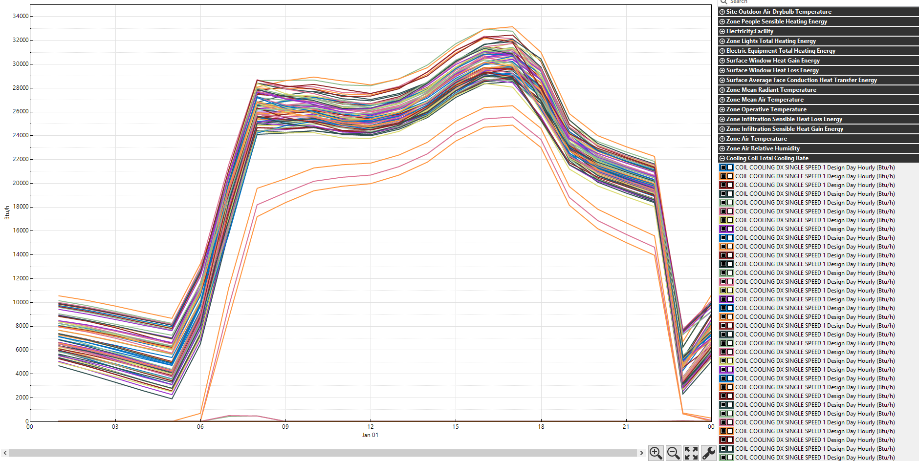
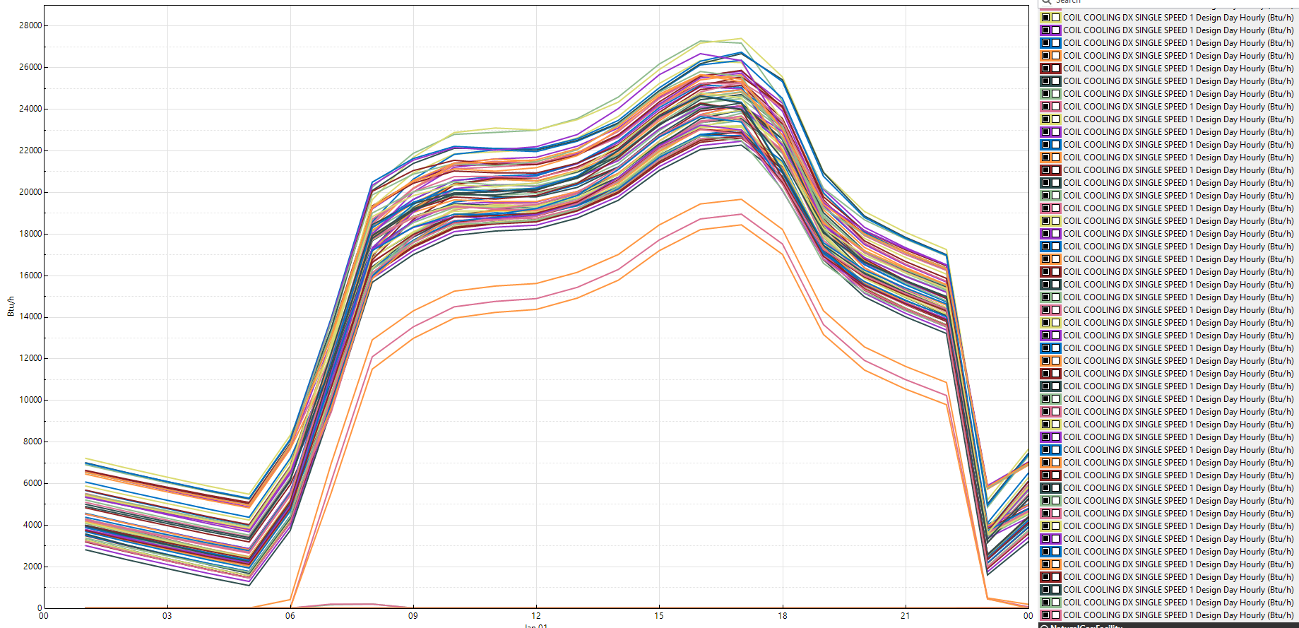
  1. In the Output Variable: Cooling coil sensible cooling rate the highest value for all de design days is 27500 BTU/h (2.3 Tons). image description

Is there anything that I am doing wrong or missing?

I don’t understand why the cooling coil capacity from the air loop detail (second pic) is 5.3 Tons. it shouldn’t be something about 2.75 tons (Cooling coil total cooling capacity maximum value from the output variable).

Any help will be appreciated.

edit retag flag offensive close merge delete

2 Answers

Sort by » oldest newest most voted
0

answered 2021-10-06 12:41:28 -0500

I have struggled with this as well. I don't think it has to do with the "Cooling Supply Air Flow Rate Per Unit Cooling Capacity". This value will affect the sizing of the system airflow rate, not the cooling capacity.

The best I can come up with is that the autosizing parameters that are used for sizing the dx coil are at the rated conditions, not the design day conditions. (rated conditions = the conditions used for calculating the performance curves) If you look at the EnergyPlus input/output reference (https://energyplus.net/assets/nrel_cu...) for any of the Coil:Cooling:DX objects, you will note that the Field: Gross Rated Total Cooling Capacity is calculated at the rated conditions. It does not calculate based on your weather file or design day file. The other issue is that autosize selects the maximum system airflow. Often the maximum airflow will be in heating, not cooling. The default rated conditions are:

image description

So, here is an example calculation:

image description

edit flag offensive delete link more

Comments

Thanks for your reply. By the way I have seen your videos in your youtube channel. Do you have a work flow to calculate cooling loads? I always end up doble checking my results in Trace700 since most of the time my cooling loads are lower in Openstudio-Energyplus.

obuchely's avatar obuchely  ( 2021-10-07 14:43:04 -0500 )edit

Yes, I usually back check using rules of thumb (ie. cfm/sqft ranges 0.7-1.5, btu/hr = cfm1.08supply air delta-T, simple outside air mixing calc, btu/hr/sqft, etc.).

I also encountered differing loads when I switched from T700 to EnergyPlus (Trace 3D+). Trane's engineers gave me the explanation that EnergyPlus uses different, more advanced calculation algorithms than T700. For example, it accounts for heat storage in materials, radiative effects, and solar position/shading whereas T700.

Ski90Moo's avatar Ski90Moo  ( 2021-10-12 22:18:13 -0500 )edit
0

answered 2021-10-05 12:09:08 -0500

Greg Estep's avatar

Good afternoon, I'm not following this exactly, as I have been using Trane Trace 3D+, but I ran into a situation where the coil capacities were being sized much larger than the calculated sensible and total loads. This is because energy plus has CFM/ton (volumetric flow rate to capacity) ratio limits. This means that if your required airflow is greater than the CFM/ton range, then the coil capacity will be upsized. Looking at your airloops detail, I see you have a maximum OA of 1596cfm. Is it possible that you are bringing over 3000CFM into your terminal unit and across the coil? If so, your CFM/ton = 3000/2.75 = 1090. This is probably exceeding the Terminal unit range limits and causing the increased capacity.

edit flag offensive delete link more

Comments

I should clarify, that this comment is for terminal units (zone level VRF or WSHP) with a DOAS system ducted directly to the return mixing boxing box. I'm not sure what system you are using. Perhaps just a rooftop.

Greg Estep's avatar Greg Estep  ( 2021-10-07 07:56:26 -0500 )edit

Thanks. Have you compared your Trace 3D plus results with other software (Trace700)?

obuchely's avatar obuchely  ( 2021-10-07 14:46:33 -0500 )edit

No. I know that this happens because it is a warning in the energyplus error file.

Greg Estep's avatar Greg Estep  ( 2021-10-11 12:11:59 -0500 )edit

Your Answer

Please start posting anonymously - your entry will be published after you log in or create a new account.

Add Answer

Careers

Question Tools

4 followers

Stats

Asked: 2021-10-02 09:51:13 -0500

Seen: 474 times

Last updated: Oct 06 '21