Question-and-Answer Resource for the Building Energy Modeling Community
Get started with the Help page
Ask Your Question
2

Some confusions about Ground Source Heat Pump in OS

asked 2021-03-25 20:42:44 -0500

wjsjch's avatar

updated 2021-03-26 09:48:47 -0500

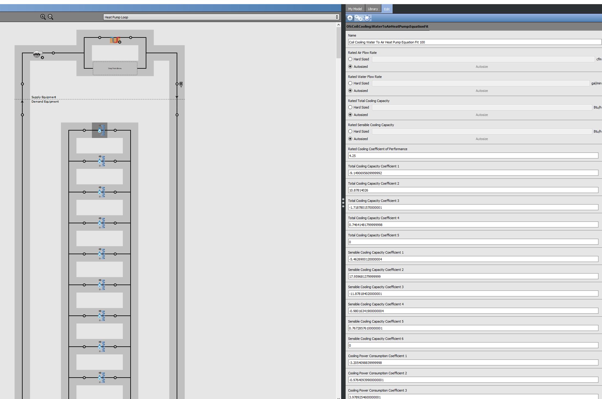
  1. In OS, the cooling and heating module of heat pump are separated. So it seems that I have to create two plant loop for cooling and heating respectively. But it brings the problem that there're two circulation pumps, for heating and cooling respectively, while in fact cooling and heating use the same pump. So how can I solve this problem?

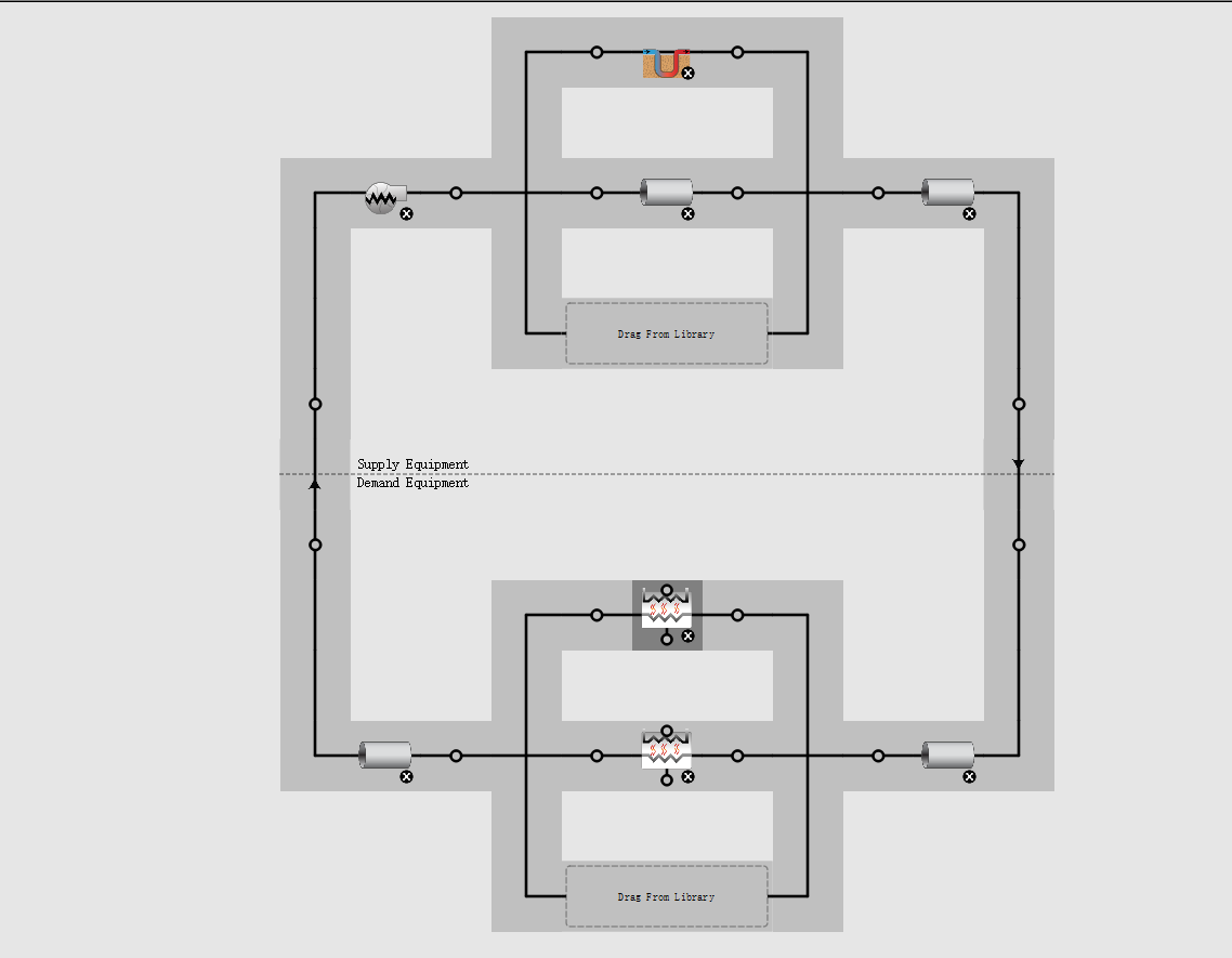
2.In the condenser loop, can I model it like the screenshot shows? If can't, should I create two condenser loops for heating and cooling respectively? But if two condenser loops are created, the scenario of duplicated pumps occurs again.It really confused me! image description

edit retag flag offensive close merge delete

2 Answers

Sort by ยป oldest newest most voted
0

answered 2021-03-26 08:22:07 -0500

JKavanaugh's avatar

updated 2021-03-26 15:20:50 -0500

You don't need to make separate loops for heating and cooling. The whole point of a common ground loop (where all heat pumps are connected to the same loop) is that the loop can provide simultaneously heating and cooling as required by the heat pump's zone loads. If a heat pump has a call for cooling, then there will be no flow through the heating coil of that heat pump. In reality, this heat pump will only have one water coil, but Energy Plus models a water source heat pump with two coils (I'm sure there's a calculation reason for this). If a single condenser loop is causing problems in your model (i.e., too high or too low loop temperatures), then your ground loop object may not be sized properly.

Edit: I'm not sure what you are trying to accomplish by having separate loops connected with heat exchangers. I run models all the time with a single ground loop connected to both heating and cooling coils of the heat pumps and have no problems. My recommendation is to have a single ground loop that is connected to the heating and cooling coils of the model's heat pumps. See below for a screenshot of a typical model I use. The coil I have highlighted is one of the heat pump's cooling coils. All of the heating coils for the heat pumps are located further down the diagram and are connected in parallel to the cooling coils. There is a single pump with no ground loop bypass, and the setpoint manager is of the "Follow Node Temperature" type, and it follows the node temperature immediately downstream of it (which is the temperature entering the heat pumps.

image description

edit flag offensive delete link more

Comments

little remark if you don't make separate loops you will need to take the right setpoint manager. Because a scheduled setpoint manager won't do the job because in mid-season you have heating and cooling on the same day.That's the reason also you find online almost always separated loops of heating and cooling it makes modelling easier.

student's avatar student  ( 2021-03-26 11:37:25 -0500 )edit

The point of the ground loop system is to allow for simultaneous heating/cooling, just like a closed-loop system with a cooling tower and boiler. You size the ground loop and control the pumps to maintain a set temperature range, and each heat pump can absorb or reject heat based on the zone load. Multiple loops add unnecessary complexity to the model and is not reflective or real conditions. You'll never have a separate loop for heating and cooling, in fact, it's a bad idea. Heat rejected to the loop should also be removed in order to balance the load to avoid long term temperature rise.

JKavanaugh's avatar JKavanaugh  ( 2021-03-26 12:45:38 -0500 )edit

@JKavanaugh I understand what you are saying but how can it be possible that the source loop with ground heatexchanger has no flow in it? While cooling or heating is active. Because that is in our OS file the case. (you can find the file in my other answer.)

student's avatar student  ( 2021-03-26 13:57:53 -0500 )edit

The heat pump object will set it's heating coil to 0 gpm when the unit is in cooling, and vice-versa in heating. There will be no demand for flow on the ground loop for whichever coil is not currently in use.

JKavanaugh's avatar JKavanaugh  ( 2021-03-26 14:01:42 -0500 )edit

I understand what you say, but what we have is an zero flow in the source loop the entire year. There is well flow in the heating loop (winter) and cooling flow in summer.

student's avatar student  ( 2021-03-26 14:40:45 -0500 )edit
0

answered 2021-03-26 07:15:37 -0500

student's avatar

updated 2021-03-26 07:23:14 -0500

We also made a model with a ground heatexchanger. It is best that you create to separated loops one for heating and one for cooling. If you want to know the total energy consumption then you just need to take the sum of both pumps. You can try to make one loop and place the heating and cooling in that one loop but I don't know if that is gone give good results.

You will also need a setpoint manager I suggest follow ground temperature or just a schedule setpoint manager.

We made 3 loops but had a problem with the flow in the loop (with heatexchanger) the flow was zero what is really weird because in the heating and cooling loop there was waterflow that had heating and cooling. So if you made your changes, you may update me with your results.

edit flag offensive delete link more

Comments

So, you finally made 4 loops (heating, cooling, and two loops with heat exchanger) in total?

wjsjch's avatar wjsjch  ( 2021-03-26 07:44:29 -0500 )edit

no, we have 3 loops. 1 source loop and one cooling and one heating loop. I will upload my file so you can see what we did. We have a problem with the flow in the loops but maybe you don't have that. you may update me with your findings. here you find our OS file in 3.1.0 I also uploaded the EPW file we used

student's avatar student  ( 2021-03-26 10:42:48 -0500 )edit

Wow! Thanks for your assistance! I'm eager to share my findings with you, while I'm not sure whether I'm can find them.

wjsjch's avatar wjsjch  ( 2021-03-26 19:28:27 -0500 )edit

I've run your model but I find that all three pumps have water flow. The water flow of Var Spd Pump, which I believe is the pump for source loop with heat exchanger, is 0.00135m3/s.

By the way, I have a question about your lutchcircuit. It seems that the Indirect Evap Cooler is not connected to any other loop and I have no idea how it works.

wjsjch's avatar wjsjch  ( 2021-03-26 20:35:38 -0500 )edit

@wjsjch would you be able to send a screenshot of the flow you get in Var Spd Pump (your 0.00135m3/s) to sebastien.devriese@student.kuleuven.be? Which output variable did you use to get the flow of the Var Spd Pump? (I look at pump mass flow rate) I have uploaded a picture with the values I get.link

about your question about the indirect Evap Cooler on this link you will find all the info you need. In the transfer...

student's avatar student  ( 2021-03-27 15:18:02 -0500 )edit

Your Answer

Please start posting anonymously - your entry will be published after you log in or create a new account.

Add Answer

Careers

Question Tools

1 follower

Stats

Asked: 2021-03-25 20:42:44 -0500

Seen: 438 times

Last updated: Mar 26 '21