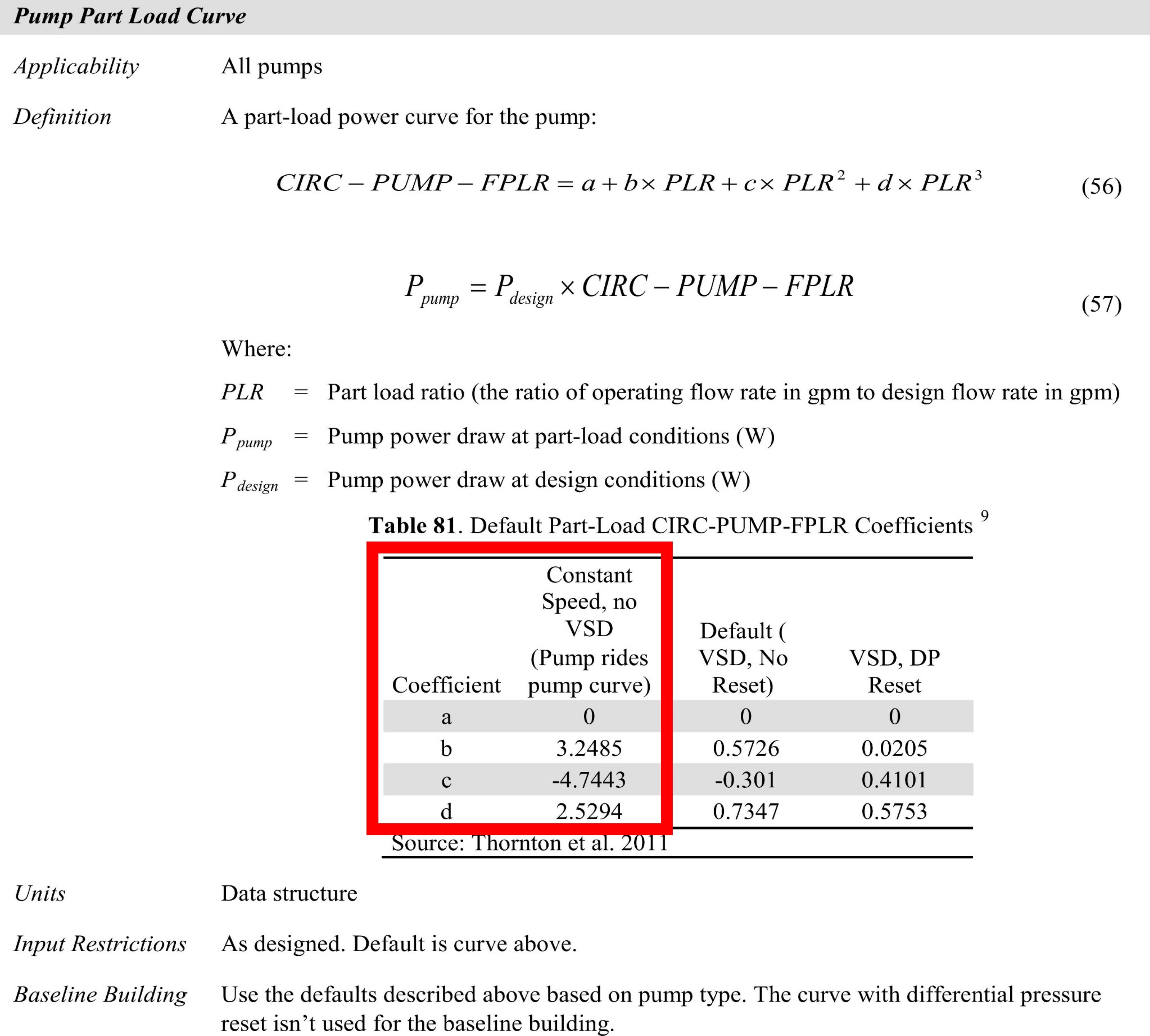
"Riding the pump curve" means the pump with constant speed drive operates at variable water flow rate. You should use Pump:VariableSpeed for the secondary pump, but you should be careful about the coefficients of the Part Load Performance Curve.
The coefficients are discribed in ANSI/ASHRAE/IES Standard90.1 Performance Rating Method Reference Manual.
The primary pump has a constant water flow rate. Pump:ConstantSpeed should be used.
Please refer to the input example below for each parameter.
Pump:ConstantSpeed,
    chiller1 ChW Branch Pump,!- Name
    chiller1 ChW Pump Inlet, !- Inlet Node Name
    chiller1 Chw Inlet,      !- Outlet Node Name
    autosize,                !- Design Flow Rate {m3/s}
    75384,                   !- Design Pump Head {Pa}
    autosize,                !- Design Power Consumption {W}
    0.9,                     !- Motor Efficiency
    0,                       !- Fraction of Motor Inefficiencies to Fluid Stream
    Intermittent,            !- Pump Control Type
    ,                        !- Pump Flow Rate Schedule Name
    ,                        !- Pump Curve Name
    ,                        !- Impeller Diameter {m}
    ,                        !- Rotational Speed {rev/min}
    ,                        !- Zone Name
    ,                        !- Skin Loss Radiative Fraction
    PowerPerFlowPerPressure,             !- Design Power Sizing Method
    ,                        !- Design Electric Power per Unit Flow Rate {W/(m3/s)}
    1.38888888888889,        !- Design Shaft Power per Unit Flow Rate per Unit Head {W/((m3/s)-Pa)}
    Chilled Water Pump;      !- End-Use Subcategory


Pump:VariableSpeed,
    CHWloop ChW Secondary Pump,  !- Name
    CHWloop ChW Demand Inlet,!- Inlet Node Name
    CHWloop ChW Secondary Pump Outlet,  !- Outlet Node Name
    autosize,                !- Design Maximum Flow Rate {m3/s}
    150768,                  !- Design Pump Head {Pa}
    autosize,                !- Design Power Consumption {W}
    0.9,                     !- Motor Efficiency
    0,                       !- Fraction of Motor Inefficiencies to Fluid Stream
    0,                       !- Coefficient 1 of the Part Load Performance Curve
    3.2485,                  !- Coefficient 2 of the Part Load Performance Curve
    -4.7443,                   !- Coefficient 3 of the Part Load Performance Curve
    2.5294,                  !- Coefficient 4 of the Part Load Performance Curve
    autosize,                       !- Design Minimum Flow Rate {m3/s}
    Intermittent,            !- Pump Control Type
    ,                        !- Pump Flow Rate Schedule Name
    ,                        !- Pump Curve Name
    ,                        !- Impeller Diameter {m}
    ,                        !- VFD Control Type
    ,                        !- Pump RPM Schedule Name
    ,                        !- Minimum Pressure Schedule {Pa}
    ,                        !- Maximum Pressure Schedule {Pa}
    ,                        !- Minimum RPM Schedule {rev/min}
    ,                        !- Maximum RPM Schedule {rev/min}
    ,                        !- Zone Name
    ,                        !- Skin Loss Radiative Fraction
    PowerPerFlowPerPressure,             !- Design Power Sizing Method
    ,                        !- Design Electric Power per Unit Flow Rate {W/(m3/s)}
    1.38888888888889,        !- Design Shaft Power per Unit Flow Rate per Unit Head {W/((m3/s)-Pa)}
    0.25,                    !- Design Minimum Flow Rate Fraction
    Chilled Water Pump;      !- End-Use Subcategory


As far as I know, riding the pump curve simply means the pump operates at constant speed. If you know what pump make and model you have, you can plot its head rise against volume flow rate and its mechanical efficiency against flow rate. For example, head rise may vary non-linearly from 80 ft at 0 gpm to 0 ft at 500 gpm and mechanical efficiency should vary non-linearly from 0 % at 0 gpm to (also) 0 % at 500 gpm, with a peak somewhere in between, say 60% at 300 gpm. The design (rating) point should be near those 60%, where the head rise then may be 60 ft.
The "riding" is dictated by the simulation. At any given hour, the pump will need to provide a certain flow, usually different from the above 300 gpm. For example, if the required flow is 250 gpm, the head rise will be more than the above 60 ft (riding up the pump curve to the left), if it is 350 gpm, the head rise will be less than those 60 ft (riding down the curve to the right), and mechanical efficiency is typically less than at 300 gpm also. At any point, the required mechanical power is then simply the product of flow, head rise and inverse of mechanical efficiency - in suitable units.
And mechanical power multiplied by the inverse of electrical efficiency (motor efficiency) - in suitable units - then is the electrical power recorded for the pump by EnergyPlus for energy modeling purposes.I believe in the HVAC plant loop, if you simply add a constant speed pump, it will assume a "typical" pump curve and do what is needed. However, it may also be that you need to use a variable speed pump and force it somehow to operate at 100% speed, because for that, you can specify actual pump curve parameters.
This here may also help.
To be certain, the pump curve used for a variable pump in OpenStudio is not head rise or efficiency vs. flow rate, but rather mechanical power to rated mechanical power vs. flow rate to rated flow rate. So it is head rise and mechanical efficiency already combined into mechanical power. That is all EnergyPlus cares about, unless you do a complete simulation (not usually done for ASHRAE 90.1).