With a unitary system, the "Setpoint" control type requires that a setpoint manager (SPM) be applied to all coils in the unitary system. You have a single zone cooling SPM applied to the cooling coil and a single zone heating SPM applied to the heating coil, but the heating SPM has an incorrect setting for the Zone Inlet Node Name input field. It's set to "RTU Supply Outlet Node" (the unitary system's supply outlet node), when that should be "Zn1 Supply Air Node" (the zone terminal's outlet node entering the zone).
The second (weird) thing that had to change was adjusting the No Load Supply Air Flow Rate input field from 0 to some value (I used the same 0.94 $\frac{m^3}{s}$ set for heating and cooling supply flow). After some reading the input field description, I came across this important piece:
This field is only used when the unitary system operating mode is specified as continuous fan operation. ... If the unitary system operating mode is specified as continuous fan operation and this value is set to zero or this field is left blank, then the model assumes that the supply air flow rate when no cooling/heating is needed is equal to the supply air flow rate when the compressor was last operating (for cooling operation or heating operation).
The "continuous fan operation" mentioned is set by the Supply Air Fan Operating Mode Schedule Name input field. In the model, this is set to "HVAC Op Sch", which is always 1, setting "always continuous fan flow" operation. If I make a new schedule that is always 0 for "always cycling fan flow" operation, then here are the results.
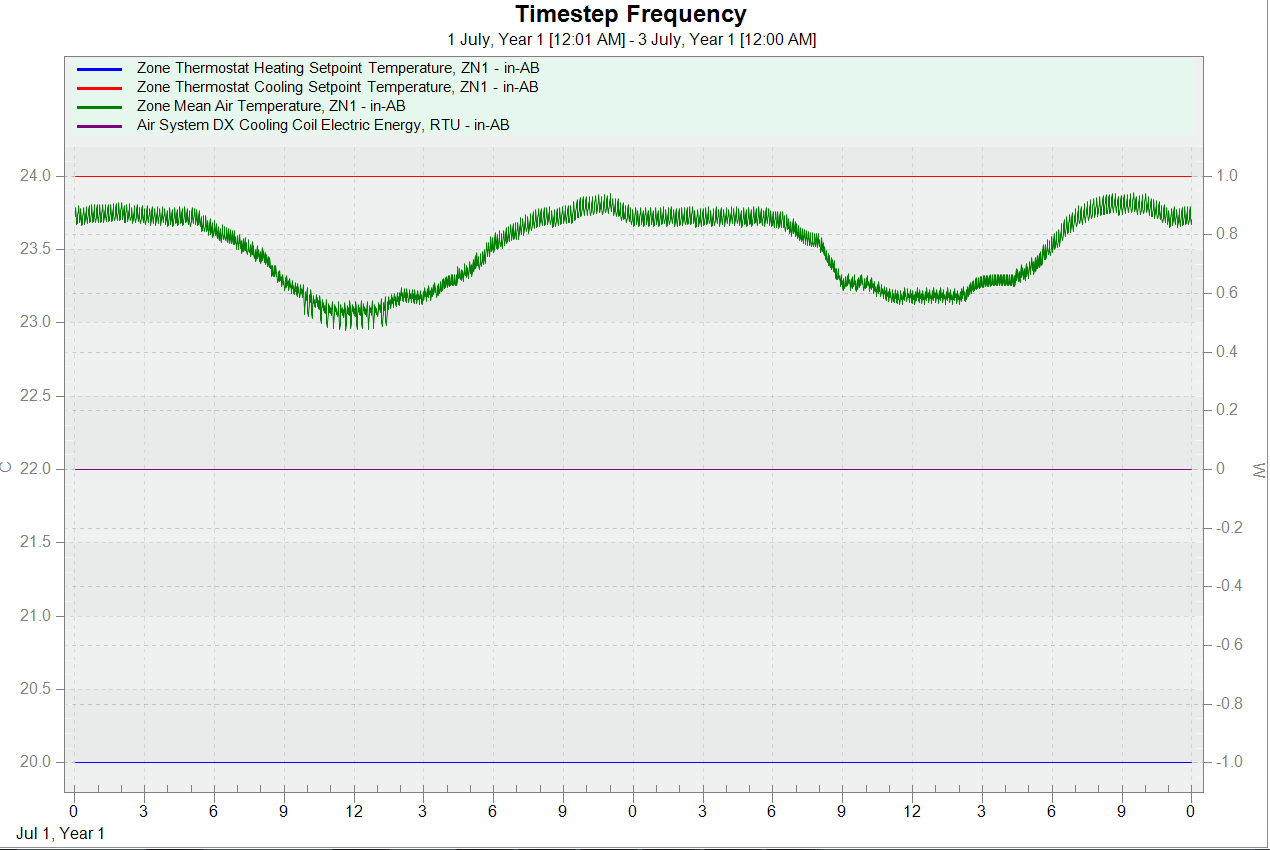
The load is apparently very small and the cooling coil hardly consumes any power to keep the zone below the cooling thermostat. This is the same if you try to include a mixed air setpoint manager for the unitary system. There is a repeating warning message related to these very low loads as well:
** Warning ** AirLoopHVAC:UnitarySystem - Iteration limit exceeded calculating part-load ratio for unit = RTU
**   ~~~   ** Estimated part-load ratio  = 1.001E-002
**   ~~~   ** Calculated part-load ratio = 9.869E-011
**   ~~~   ** The calculated part-load ratio will be used and the simulation continues. Occurrence info:
**   ~~~   **  Environment=SAN.DIEGO-BROWN.FIELD.MUNI.AP_CA_USA WMO=722904, at Simulation time=07/01 00:03 - 00:04

 ** Warning ** AirLoopHVAC:UnitarySystem "RTU" - Iteration limit exceeded calculating sensible part-load ratio error continues. Sensible PLR statistics follow.
 **   ~~~   **   This error occurred 2315 total times;
 **   ~~~   **   during Warmup 0 times;
 **   ~~~   **   during Sizing 0 times.
 **   ~~~   **   Max=9.998715E-011  Min=1.000328E-012
I'd be happy to share my updated IDF via email, if you'd like.
_9Seeaet.png "carlobianchi89")


_9Seeaet.png "carlobianchi89")
