Question-and-Answer Resource for the Building Energy Modeling Community
Get started with the Help page
Ask Your Question
2

Flow rate of Fluid-to-Fluid Heat exchanger

asked 2020-06-15 09:23:07 -0500

szsz's avatar

updated 2020-06-15 10:08:45 -0500

I have modeled primary/secondary loop with fluid-to-fluid heat exchanger according to "Plant Application Guide".
Primary loop includes district cooling & variable pump & heat exchanger and secondary loop includes LoadProfile & variable pump & heat exchanger.
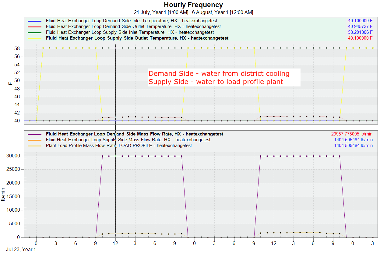
Result shows that heat exchanger demand side flow rate is not same with supply side flow rate which required from LoadProfile. Though the pump is variable one, demand side flow rate is identical for all the operating hours.
How to set heat exchanger to get identical inlet&outlet temperature and flow rate for both supply and demand side?

edit retag flag offensive close merge delete

Comments

I think load profile demands a flow rate in the secondary loop, not the primary loop, did you check that?

Mehrdad Vojdani's avatar Mehrdad Vojdani  ( 2020-06-15 14:16:04 -0500 )edit

@mehrdad Yes, heat exchanger’s supply side flow rate is identical with the load profile flow rate. But the demand side’s flow rate is a different value and constant for every hours.

szsz's avatar szsz  ( 2020-06-15 17:58:31 -0500 )edit

Nothing wrong with flow rate being different for load profile. It should be! It would be good if you attach your idf for further investigation.

Mehrdad Vojdani's avatar Mehrdad Vojdani  ( 2020-06-15 19:54:03 -0500 )edit

@mehrdad Here is the link for the idf file: ( link ). Very appreciate for your help!

szsz's avatar szsz  ( 2020-06-15 20:30:34 -0500 )edit

I couldn't come with any solution. You are using district cooling and I have no idea how the flow rate of this component is calculated! Maybe tracking the inlet temperature of district cooling helps you.

Mehrdad Vojdani's avatar Mehrdad Vojdani  ( 2020-06-15 22:16:31 -0500 )edit

1 Answer

Sort by » oldest newest most voted
2

answered 2020-06-20 10:41:34 -0500

After running your IDF, you already are getting identical temperatures between supply inlet and demand outlet for the water-to-water heat exchanger (WWHX) (see below).

image description

You are also getting the same flow rate requested by the load profile plant object on the supply side (same side of the WWHX). So it seems like your system is working as intended. The reason that you have different flow rates on the two sides of the heat exchanger is because of the different temperature differences between inlet/outlet nodes on each side (supply vs. demand) of the WWHX. Since there are two separate pumps, EnergyPlus can solve for a different flow rate in the primary loop (WWHX demand-side) due to it's different temperature difference (~0.85F in the timestep from my screenshot vs. ~18.1F for supply-side).

If you wanted to force the same flow rate on both sides of the WWHX, you would need to use EMS (looks like you've already asked about that here). Why do you want to force that?

edit flag offensive delete link more

Comments

The reason is I am now modelling two cooling plants which serve chilled water for one building based on different time. As energyplus do not support to model several connectors in one loop, I want to use heat-exchanger component to transfer exactly same condition fluid from one loop to another loop. Since the flow rate of heat exchanger is different, I was trying to use EMS to solve this issue, but it still failed. Could you please give some tips to properly model this kind of system?

szsz's avatar szsz  ( 2020-06-20 12:24:12 -0500 )edit

Your Answer

Please start posting anonymously - your entry will be published after you log in or create a new account.

Add Answer

Careers

Question Tools

2 followers

Stats

Asked: 2020-06-15 09:23:07 -0500

Seen: 352 times

Last updated: Jun 20 '20