multistage furnace net PLF vs PLR

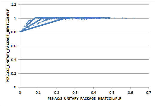
I've calculated the hourly part-load fraction (PLF) as a function of part-load ratio (PLR) of a multistage gas furnace in an EnergyPlus model. The result has many PLF values for a given PLR at low loads which does not seem right. It looks like something is happening with staging because there are 4 (maybe 5) discrete sloped lines. I've read through the Engineering Reference but still can't see how this is correct. Any help is appreciated.
Here is the curve:
Here are the outputs I used and how I calculated the values for every timestep using those outputs:
  Output:Variable,PSZ-AC:2_Unitary_Package_HeatCoil,Heating Coil Heating Rate,Timestep;

  Output:Variable,PSZ-AC:2_Unitary_Package_HeatCoil,Heating Coil Gas Rate,Timestep;

PLR = PSZ-AC:2_Unitary_Package_HeatCoil,Heating Coil Heating Rate / Design Size Stage 4 Nominal Capacity
PLF = PSZ-AC:2_Unitary_Package_HeatCoil,Heating Coil Heating Rate / (PSZ-AC:2_Unitary_Package_HeatCoil,Heating Coil Gas Rate * Nominal Efficiency)
Here are the relevant objects:
  AirLoopHVAC:UnitaryHeatPump:AirToAir:MultiSpeed,
    Core Zone Multi Stage Gas Furnace,  !- Name
    ALWAYS_ON,               !- Availability Schedule Name
    PSZ-AC:2_OA-PSZ-AC:2_Unitary_PackageNode,  !- Air Inlet Node Name
    PSZ-AC:2 Supply Equipment Outlet Node,  !- Air Outlet Node Name
    Core_Retail,             !- Controlling Zone or Thermostat Location
    Fan:ConstantVolume,      !- Supply Air Fan Object Type
    PSZ-AC:2_Unitary_Package_fan,  !- Supply Air Fan Name
    BlowThrough,             !- Supply Air Fan Placement
    ALWAYS_ON,               !- Supply Air Fan Operating Mode Schedule Name
    Coil:Heating:Gas:MultiStage,  !- Heating Coil Object Type
    PSZ-AC:2_Unitary_Package_HeatCoil,  !- Heating Coil Name
    -100,                    !- Minimum Outdoor Dry-Bulb Temperature for Compressor Operation {C}
    Coil:Cooling:DX:MultiSpeed,  !- Cooling Coil Object Type
    PSZ-AC:2_Unitary_Package_CoolCoil,  !- Cooling Coil Name
    Coil:Heating:Fuel,       !- Supplemental Heating Coil Object Type
    PSZ-AC:2_SupplementaryHeatingCoil,  !- Supplemental Heating Coil Name
    0,                       !- Maximum Supply Air Temperature from Supplemental Heater {C}
    -100,                    !- Maximum Outdoor Dry-Bulb Temperature for Supplemental Heater Operation {C}
    ,                        !- Auxiliary On-Cycle Electric Power {W}
    ,                        !- Auxiliary Off-Cycle Electric Power {W}
    ,                        !- Design Heat Recovery Water Flow Rate {m3/s}
    80,                      !- Maximum Temperature for Heat Recovery {C}
    ,                        !- Heat Recovery Water Inlet Node Name
    ,                        !- Heat Recovery Water Outlet Node Name
    autosize,                !- No Load Supply Air Flow Rate {m3/s}
    4,                       !- Number of Speeds for Heating
    2,                       !- Number of Speeds for Cooling
    8.592,                   !- Heating Speed 1 Supply Air Flow Rate {m3/s}
    8.592,                   !- Heating Speed 2 Supply Air Flow Rate {m3/s}
    8.592,                   !- Heating Speed 3 Supply Air Flow Rate {m3/s}
    8.592,                   !- Heating Speed 4 Supply Air Flow Rate {m3/s}
    8.592,                   !- Cooling Speed 1 Supply Air Flow Rate {m3/s}
    8.592,                   !- Cooling Speed 2 Supply Air Flow Rate {m3/s}
    8.592;                   !- Cooling Speed 3 Supply Air Flow Rate {m3/s}

  Coil:Heating:Gas:MultiStage,
    PSZ-AC:2_Unitary_Package_HeatCoil,  !- Name
    ALWAYS_ON,               !- Availability Schedule Name
    PSZ-AC:2_Unitary_PackageHeatCoil air inlet,  !- Air Inlet Node Name
    PSZ-AC:2_Unitary_PackageSuppHeatCoil air inlet,  !- Air Outlet Node Name
    PSZ-AC:2_Unitary_PackageCoolCoil air inlet,  !- Temperature Setpoint Node Name
    Single- of Multi-stage PLF,  !- Part Load Fraction Correlation Curve Name
    ,                        !- Parasitic Gas Load {W}
    4,                       !- Number of Stages
    0.744,                   !- Stage 1 Gas Burner Efficiency {W/W}
    autosize,                !- Stage 1 Nominal Capacity {W}
    ,                        !- Stage 1 Parasitic Electric Load {W}
    0.744,                   !- Stage 2 Gas Burner Efficiency ...