Question-and-Answer Resource for the Building Energy Modeling Community
Get started with the Help page
Ask Your Question
3

Model vertical helical ground heat exchanger in EnergyPlus

asked 2020-02-20 18:27:10 -0500

mldichter's avatar

updated 2020-02-28 12:03:12 -0500

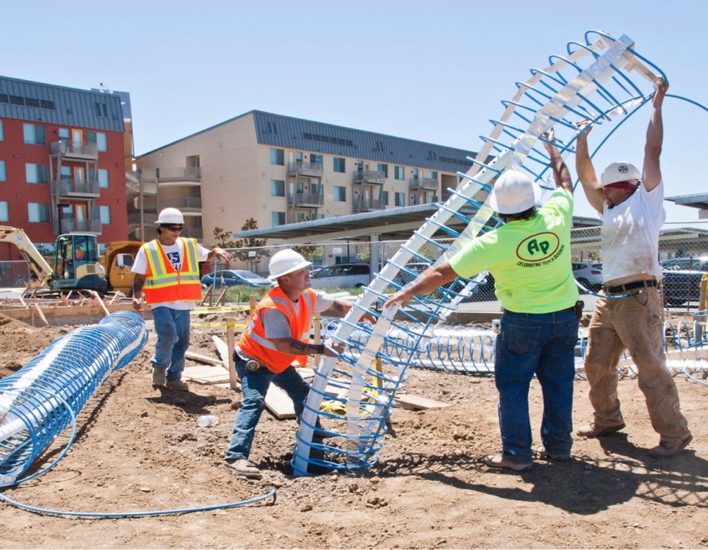
We have an experimentally validated model of a helical ground heat exchanger, like this.

image description

A PhD student spent a few years working on this project, and the next step is for him to model it in EnergyPlus. We have a major problem though since the closest object in EnergyPlus is the U-tube and the results don't agree. We're pretty sure the discrepancy comes from the grout in the borehole lying between the dirt and U-tube, versus the helix which is right against the edge of the borehole. The PhD student found that the mean water temperature in the helix is almost the same as the mean borehole wall temperature and the grout plays almost no role.

The PhD student is freaking out a little bit, so I'm trying to help him finish. We already tried making an impossibly conductive grout material but that is causing very bad looking errors in EnergyPlus. I found the GroundHeatExchangers.cc file, which is very readable, and I think I could plausibly alter the code and recompile EnergyPlus to set fluid temperature based on the borehole wall temperature, but that's not an appealing solution. There's cosimulation possibilities with matlab, but can those alter things like water temperatures in plantloops?

Does anyone have any ideas how to remedy this? Doesn't have to be clean, just has to work.

POST SCRIPT
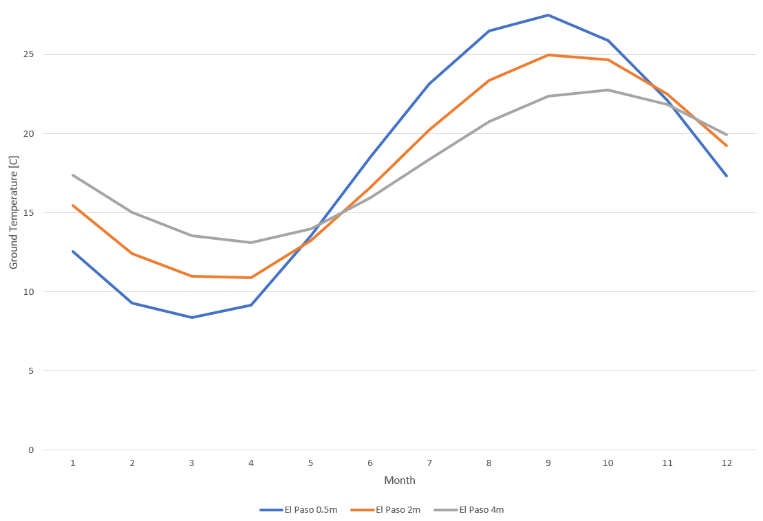
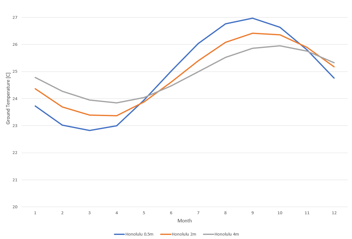
Just as a reminder to soil fluctuation, here are ground temperatures from EPW files for El Paso, TX and Honolulu, HI. The ground temperatures vary significantly at different depths without a heat exchanger. With a heat exchanger, the ground temperatures will change. This is taken account of in the GroundHeatExchangers.cc code. In the case of the U-tube, the G-functions are used to calculate the boundary temperature between the dirt and grout at the borehole wall. Part of that computation uses many previous iterations of the simulation because the ground temperatures do not stay constant. In fact, it can take months after turning off ground heat exchanger for the ground temperatures to go back to normal. After calculating the borehole wall temperature, looks like the code uses a finite element method to calculate the grout temperature at the U-tube pipe wall. Then the model actually takes into account the heat propagation through the pipe wall, and then fluid temperature is calculated. This is not a trivial problem. image description image description

edit retag flag offensive close merge delete

3 Answers

Sort by » oldest newest most voted
1

answered 2020-02-28 10:48:00 -0500

mldichter's avatar

We ended up going with the matlab and energyplus cosimulation using this matlab toolbox on github. The toolbox is able to send Output:Variable values from energyplus to matlab, and matlab is able to send new schedule values to energyplus each timestep. How much heating or cooling the GHE did to the water circulating through it was done in energyplus by DistrictCooling and DistrictHeating objects.

Working inside the HVAC iteration loop was a little bit of a kluge though. It's not clear what the inlet and outlet temperatures of the water to the GHE should be because the GHE is attached to a water source heat pump. Reaching consistent inlet outlet water temperatures between the GHE and WSHP occurs in the HVAC iteration loop in energyplus. As far as I know, communication between matlab and energyplus only occurs once per time step and not at each iteration of the HVAC iteration loop. To get around this, the schedules give some EMS code a linear fit of the inlet outlet water temperature relationship at the current timestep. The EMS code then sets the outlet temperature of the DistrictCooling and DistrictHeating objects using the linear fit and the GHE water inlet temperature from the current iteration of the HVAC iteration loop. The HVAC iteration loop eventually converges with the final inlet and outlet water temperatures for that timestep sent to matlab.

edit flag offensive delete link more
0

answered 2020-02-21 08:32:35 -0500

JKavanaugh's avatar

How deep are the boreholes? If they are fairly shallow, it's probably reasonable to assume that the ground temperature fluctuates annually in a similar way that a surface water pond would. I think anchapin's idea of using the GroundHeatExchanger:Pond would be a good idea in this case. You may also try the horizontal loop model and compare the two.

edit flag offensive delete link more

Comments

@JKavanaugh The picture is in the post is actually from the experiment. You can see the complex where out lab is located in the background. If memory serves correctly, I think they were around 5m long. Some of the holes may have been different lengths too. I wasn't involved in this project until now. Anyway, thanks for replying, but those won't work. Modeling of ground heat exchangers is not a trivial problem. I expect the pond model to be way too good of a heat exchanger compared to dirt, and we don't know what temperature the pond should be.

mldichter's avatar mldichter  ( 2020-02-21 11:24:47 -0500 )edit

The pond model should take temperature fluctuation of the pond water into account, much like the ground temperature variations of your charts. You are correct in that water would be a much better heat exchanger, but the model may allow you to make the thermal capacity of water much worse by changing the pond area and depth. The pond or slinky model are not ideal for your situation, but they are the closest analogs to what is currently available in E+. I don't think you're going to get any better results trying to manipulate the vertical U-tube model.

JKavanaugh's avatar JKavanaugh  ( 2020-02-21 15:32:17 -0500 )edit

From the E+ reference on the Slinky model:

"This model reuses much of the same code including the load aggregation and temperature response caluclations which are described above in the GroundHeatExchanger:Vertical model. As a result, that section can also be used as reference material. This model is unique in that it generates it’s own temperature response factor g-functions, rather than relying on the other software or data to generate the g-functions."

JKavanaugh's avatar JKavanaugh  ( 2020-02-21 15:32:43 -0500 )edit

@JKavanaugh I know you're trying to be helpful, but these models are fundamentally different. The temperature of the dirt varies vertically and radially for the U-tube, but I suspect all the water in the pond is at the same temperature. Yes, any ground heat exchanger model will approximate every ground heat exchanger, but we can't publish that. Just ask yourself, "If you read a research paper where experimental data from an actual U-tube ground heat exchanger was said to be equivalent with a modeled pond heat exchanger, would you make financial decisions based on the results?" No.

mldichter's avatar mldichter  ( 2020-02-21 16:18:38 -0500 )edit
1

I'm confused, I thought your experimental data comes from the helical heat exchanger shown in the photo, is that not the situation?

The point I'm trying to make is that I would think that actual operation of a helical heat exchanger with borehole depths of 5m would be closer to the E+ model of a pond or slinky heat exchanger, rather than the E+ model of a vertical U-tube. The helical exchanger will be effected by annual fluctuations in the ground temperature in the relatively shallow ground in much the same way a pond or slinky heat exchanger would.

JKavanaugh's avatar JKavanaugh  ( 2020-02-21 16:43:36 -0500 )edit
0

answered 2020-02-21 07:34:15 -0500

Here are some ideas:

  1. Try GroundHeatExchanger:Slinky (seems more similar to the helical ground heat exchanger than the U-tube type)
  2. Try to determine GroundHeatExchanger:ResponseFactors to input into Energyplus that would match the experimental data that you have.
  3. Try GroundHeatExchanger:Pond since the water temperature leaving the pond heat exchanger should be roughly equal to the pond temperature. You might be able to approximate the borehole wall temperature with the pond.
edit flag offensive delete link more

Comments

1

@anchapin
1) The slinky is a way different model from a vertical bore. It just won't work.
2) We do have the correct response factors for calculating the borehole wall temperature, but the problem lies with the C code then using a finite element method to calculate the heat distribution in the grout for the purpose of determining the grout U-tube boundary temperature. The helix is pretty much against the borehole wall, so that's no good.
3) I expect the pond model to be way too good of a heat exchanger compared to dirt, and we don't know what temperature the pond should be.

mldichter's avatar mldichter  ( 2020-02-21 12:19:53 -0500 )edit

Your Answer

Please start posting anonymously - your entry will be published after you log in or create a new account.

Add Answer

Careers

Question Tools

2 followers

Stats

Asked: 2020-02-20 18:27:10 -0500

Seen: 394 times

Last updated: Feb 28 '20