Question-and-Answer Resource for the Building Energy Modeling Community
Get started with the Help page
Ask Your Question
3

How to model Solar Tubes without a ceiling cavity?

asked 2020-01-02 12:29:26 -0600

mldichter's avatar

updated 2020-10-28 08:35:24 -0600

As far as I know, the DaylightingDevice:Tubular object must reference two FenestrationSurface:Detailed objects, each of which must be embedded in a BuildingSurface:Detailed object. Is there a way to model a solar tube with a dome that is attached to the roof surface, but the diffuser surface is free floating in the space?

POST SCRIPT
Here's an obvious idea. Can I just have a rectangular prism attached to the ceiling that extends down into the space? I could put the two fenestration surfaces on the top and bottom of the box. However, I then have to split up the roof into a lot of rectangles to keep all the surfaces convex. Is there a better way? Does a fake bottom surface made of air simulate correctly in EnergyPlus?
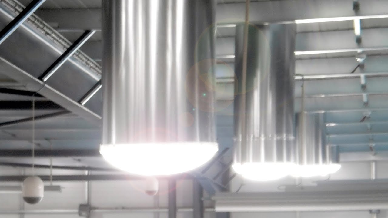
image description

edit retag flag offensive close merge delete

Comments

@Aaron Boranian I saw your answer about Construction:AirBoundary in this post and was wondering if you think that would work well for this case of putting in light tubes in a space with no zone cavity for the light tube cylinder to travel through.

mldichter's avatar mldichter  ( 2020-09-23 18:01:56 -0600 )edit

2 Answers

Sort by ยป oldest newest most voted
0

answered 2020-10-27 18:46:29 -0600

mldichter's avatar

I ended up using a ZoneCrossMixing object so there was energy flow between the zones and a Material:NoMass object with the bare minimum Thermal Resistance [m2-K/W] = 0.001000 + 0.0001 just to be safe. I couldn't use a metal sheet because I am also modeling PCM in the IDF, but this seems to work just as well. The temperature on either side of my surface to put the light tube diffusers in should have the same temperature on either side anyway from the ZoneCrossMixing object.

edit flag offensive delete link more
1

answered 2020-09-24 08:54:15 -0600

I would have recommended using the Construction:AirBoundary object, but from the Input Output Reference it says that a base surface with this construction assigned cannot contain fenestration (the diffusers). An alternative to the air boundary construction would be using a standard Construction object that is comprised of one material layer that is thin and won't block much heat transfer or store much heat. Either way, you will have two zones separated by this base surface containing the diffuser fenestration surfaces.

This will likely be faster and easier than your post-script idea of drawing rectangular prisms from the ceiling down to the diffusers, mainly because of the extra time to draw 5 base surfaces (4 walls, 1 "floor") for each diffuser instead of one base surface containing all diffusers. I will note that you do not need to split the roof surface for convexity issues. That applies to the outermost edges of the base surface only -- the addition of skylights in a roof surface make "holes" in the middle of the roof, but that doesn't change the convexity of the roof. This applies to the TDD domes drawn within the roof for either approach.

edit flag offensive delete link more

Your Answer

Please start posting anonymously - your entry will be published after you log in or create a new account.

Add Answer

Training Workshops

Careers

Question Tools

1 follower

Stats

Asked: 2020-01-02 12:29:26 -0600

Seen: 371 times

Last updated: Oct 27 '20