Question-and-Answer Resource for the Building Energy Modeling Community
Get started with the Help page
Ask Your Question
3

Ideal Air Loads in Open Studio

asked 2015-03-31 04:36:29 -0500

Carlos Vazquez's avatar

updated 2020-03-10 09:52:02 -0500

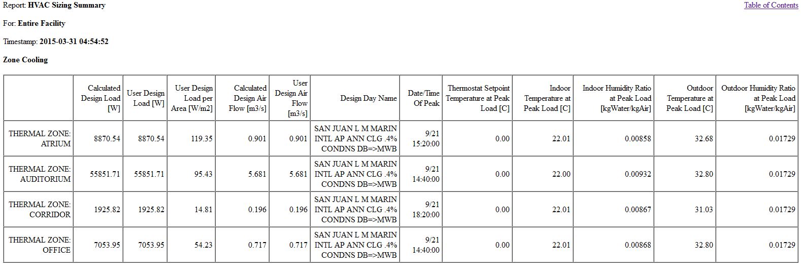
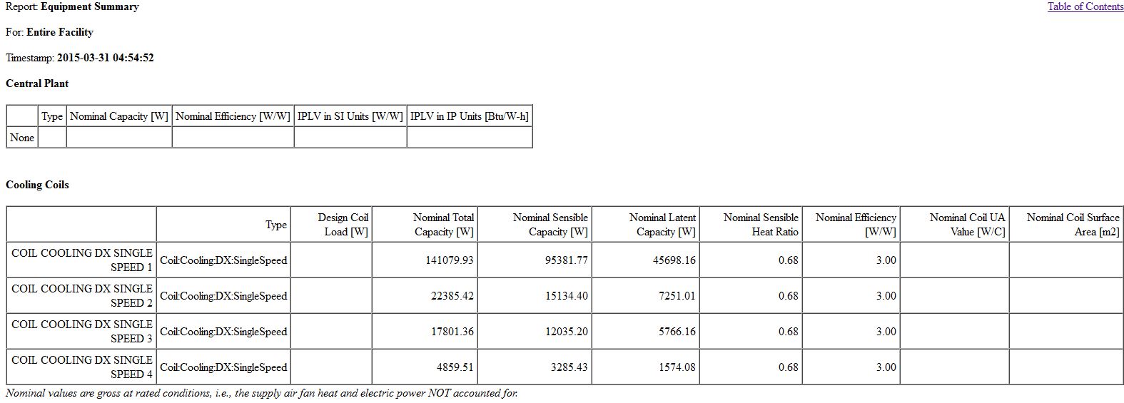
I am a Trace 700 user. I am making test models while learning Energyplus. I am establishing a workflow turning on Ideal Air Loads from the Openstudio application and make an initial simulation to test geometry. After the initial simulation, in the HVAC Sizing Summary Report I am getting cooling loads about 1/3 lower from the ones calculated with Trace 700 for the same case. However, in another simulation after defining air loops and plants in Openstudio, the sizes in the Equipment Summary Report are in line with the load calculations in Trace 700 for the same case. However, in Energyplus the loads from the HVAC Sizing Summary Report are still 1/3 from the sizes in the Equipment Summary Report. I will appreciate to know why this happens! Thank you.

HVAC Sizing Summary.JPG Equipment Summary Report.JPG

edit retag flag offensive close merge delete

Comments

I believe this post may help here

keb's avatar keb  ( 2015-03-31 08:55:26 -0500 )edit
1

I have read that post before making my question. And I made a test with a separate simulation with an idf file in the Energyplus engine. In my test I included the Outdoor Air Loads object within the Ideal Loads Object. And still got the same results: Ideal Cooling Loads around 1/3 of the ones calculated with Trace 700 for the same case.

Carlos Vazquez's avatar Carlos Vazquez  ( 2015-03-31 09:07:36 -0500 )edit

I'm working with Trace 700 and EnergyPlus (Open Studio) for 2 years. The problem with difference of the thermal load between two softwares always was a problem. At present, we are working in a simulation to LEED, and the results OpenStudio are 50 TR while the results of TRACE 700 are 150 TR, exactly 1/3. I'm already considering ventilation loads in Open Studio because I am reading the Evaporator Colling Load of the chiller. Really, I don't know no more what is happening. Maybe, other person that have more experience and success with two softwares could analyse the models to suggest corrections

Geraldo Pithon's avatar Geraldo Pithon  ( 2015-03-31 17:12:31 -0500 )edit

Another consideration is important ... the thermal load obtained by Trace 700 is usually much closer to our estimates for HVAC projects in our localities, where the climate is hot and humid is high.

Geraldo Pithon's avatar Geraldo Pithon  ( 2015-03-31 17:19:06 -0500 )edit

Exact Carlos! I'm working this way, but it has generated many questions because my chiller is with a super sized capacity. About IdealAirLoads feature, it will not consider the loads of ventilation because IdealAirLoads analysis is to evaluate only the charges for the space itself, it does not look at the impact of air to pass through the HVAC system. Some topics already treat it in this forum and will clarify it better. It is also useful to clarify the InputOutputReference manual. I suggest using a hypothetical air conditioning system to analyze the actual heat load to be removed by the coil.

Geraldo Pithon's avatar Geraldo Pithon  ( 2015-04-01 08:02:06 -0500 )edit

3 Answers

Sort by » oldest newest most voted
3

answered 2015-04-09 09:17:52 -0500

"However, in Energyplus the loads from the HVAC Sizing Summary Report are still 1/3 from the sizes in the Equipment Summary Report. I will appreciate to know why this happens! "

The Design Load in the HVAC Sizing Summary is the zone sensible cooling or heating load only. It does not include any ventilation loads (outdoor air which is added by the HVAC system, this includes outdoor air added by ideal loads air systems). It also does not include any latent loads. The Equipment Summary and Component Sizing Summary report the capacity of the individual system components which includes latent and ventilation loads.

Regarding the differences in loads between programs, the ground heat loss is a common mistake. Any surface with "Ground" as the outside boundary condition will use the Site:GroundTemperature:BuildingSurface value as the outside surface temperature for that surface. The defaults for this as 18C (64.4F) which is nearly always wrong. These ground temperatures must be customized for the application or use one of the more advanced ground surface boundary conditions.

edit flag offensive delete link more

Comments

Thank you Mike for your post. And you are absolutely right with the ground heat loss! For peak cooling loads I have been getting more confidence with the results using the Site:GroundDomain and Site:GroundTemperature:FCfactorMethod objects.

Carlos Vazquez's avatar Carlos Vazquez  ( 2015-04-09 09:36:16 -0500 )edit

And to add to this, in order to even get a latent cooling load to appear in EnergyPlus Results' Equipment Summary, I had to add a 'dummy' PTAC unit. In the cooling coils section, I then got a Nominal Sensible Capacity and a Nominal Latent Capacity, which hopefully do not include any safety factors.

IanVG's avatar IanVG  ( 2023-11-07 10:25:24 -0500 )edit
2

answered 2015-03-31 10:44:13 -0500

updated 2015-03-31 11:07:11 -0500

keb's avatar

For Ideal Air Loads runs in OpenStudio outdoor air isn't included which will impact the heating and cooling loads vs. running with a full system. The first thought about differences between Trace results and your OpenStudio run with the full system could be a change in the Cooling sizing factor. By default OpenStudio uses 1.25 for heating sizing factor, and 1.15 for cooling sizing factor. Another thing to confirm is that you are running with the same design day files in Trace vs. OpenStudio. The difference on how the tools handle geometry could have an impact on sizing (but I wouldn't expect 1/3 off) due to that.

Just out of interest, do you see similar differences in heating sizing?

edit flag offensive delete link more

Comments

I'm not sure about the differences in heating loads. Actually, the model is for a climate with no heating degree days. Hot and humid all the year. But I think I have identified the problem but do not have an explanation. The "Peak Cooling Sensible Heat Gain Components" report is showing 0 (zero) heat gain through opaque surfaces. I'm sure there are around 12 ton of sensible loads through roofs and walls that are not being accounted. I have checked all the geometry and everything looks good. Any hints about why is this happening?

Carlos Vazquez's avatar Carlos Vazquez  ( 2015-04-01 12:11:38 -0500 )edit

Looks like the issue is related to conflict between cooling and heating thermostat schedules. I'm working to setup the thermostats schedules again.

Carlos Vazquez's avatar Carlos Vazquez  ( 2015-04-01 13:40:42 -0500 )edit

@Carlos Vazquez, related to the opaque surfaces, make sure that the boundary condition is ground and outdoors where it should be. If you aren't seeing any heat gain through them, it almost seems like they are all set to a boundary condition of adiabatic.

David Goldwasser's avatar David Goldwasser  ( 2015-04-01 14:38:31 -0500 )edit

I have the same problem. My cooling load in trace is 3 times bigger than the one in e+. I can see that the fenestration solar y almost 3 times more in e+. I have the same U value ans SHGC in both models

obuchely's avatar obuchely  ( 2015-07-20 20:09:30 -0500 )edit

I encountered a problem in which the heat gain through opaque surfaces in the summer is zero and the heat removal is negative, meaning that heat is being removed through opaque surfaces, but is shouldn't be so since I have set zone air temperature to 24℃ in Cooling Setpoint Temperature. Really confused now.

W. Chiang's avatar W. Chiang  ( 2017-04-17 10:21:38 -0500 )edit
3

answered 2015-04-03 10:15:35 -0500

Carlos Vazquez's avatar

updated 2015-04-04 10:24:08 -0500

I just saw what is happening with my simulation. Is was not obvious until I saw the "Zone Component Load Summary Report". It revealed a 39% heat loss through the floor slab in contact with ground. Looks like E+ registers a peak design load through the slab on ground within the summer design day that is a heat loss instead of a heat gain in the space. My opinion is that slab on ground heat loss shall be disregarded for a peak cooling load calculation. The "Zone Component Load Summary Report" is not a default in E+. It is available as an Openstudio measure and in the IDF editor in the class "Output:Table: Summary Report". The default in the idf file is "AllSummary". It is necessary to change the field to "AllSummaryandSizingPeriod". This scenario explains why I was getting the wrong impression of having "adiabatic walls".

edit flag offensive delete link more

Your Answer

Please start posting anonymously - your entry will be published after you log in or create a new account.

Add Answer

Careers

Question Tools

7 followers

Stats

Asked: 2015-03-31 04:36:29 -0500

Seen: 3,612 times

Last updated: Apr 09 '15