Question-and-Answer Resource for the Building Energy Modeling Community
Get started with the Help page
Ask Your Question
2

Design day and VRF - Zone air temperature failed to reach AC setpoint

asked 2019-11-06 02:17:00 -0600

Eru's avatar

updated 2020-01-14 09:32:02 -0600

Hi fellas! I have a building model with several zones. I need to get the AC sizing for each zone. After I simulated the model I got the sizing but when I plot the zone air temperature there is one zone that failed to reach the setpoint temperature. As I understand, the AC sizing which is the cooling capacity for each room can provide setpoint temperature during AC on. But in this zone, there are a few hours that the temperature above it (Image 1). Then I also plot the VRF total cooling energy, in the hour that the temperature increase, the cooling energy decrease (image 2). The thing that I don't understand why the sized AC can't maintain the zone air temperature always met setpoint?
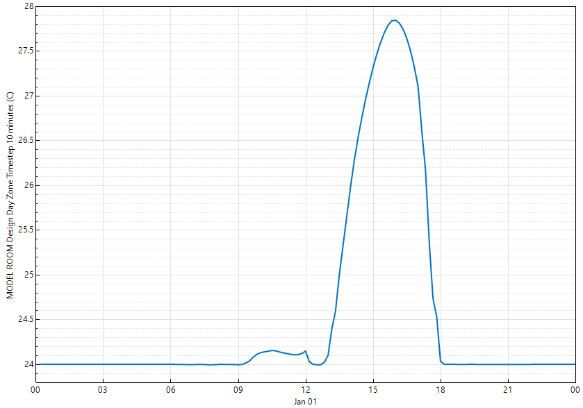
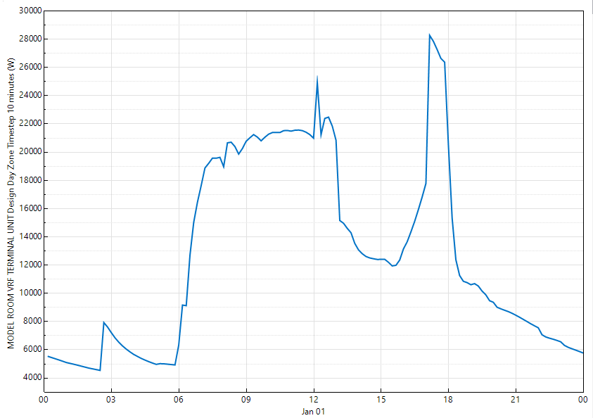
Image 1Image 2

Because the sized AC can't provide what I need so I tried to increase the cooling factor. The cooling factor of the previous simulation of 1 then I increased it to 1.15 then the cooling capacity indeed increase but the zone air temperature still failed to maintain setpoint whole time although it decreases a little bit (image 3). The cooling energy also decreases but not much as the previous simulation (image 4).
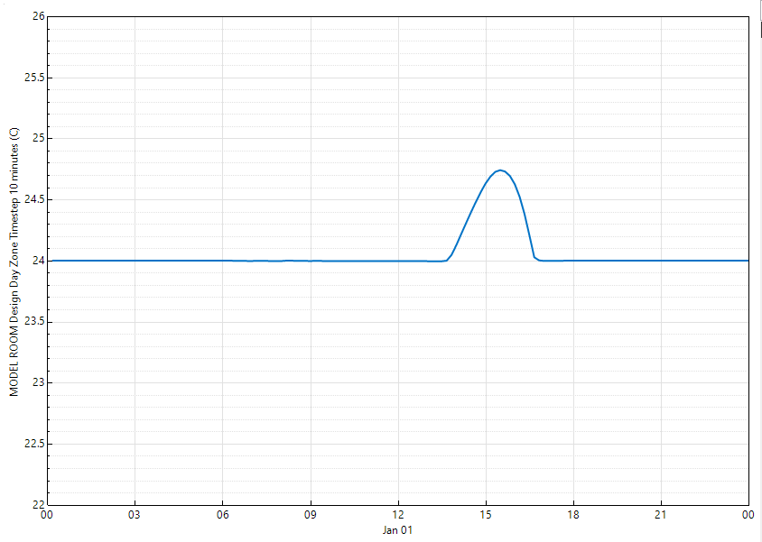
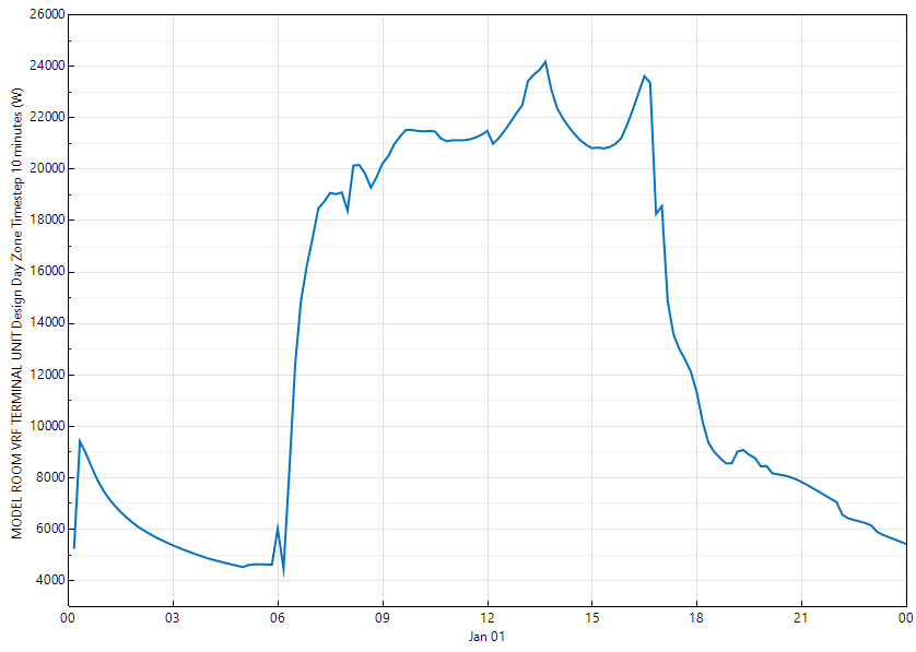
Image 3Image4

This is the AC schedule, for the sizing I used the design day (image 5) and this is the zone sizing for each room (image 6)
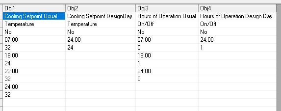
Image 5Image 6

The zone is the bigger zone which has huge fenestration also there is an inline fan (air intake) to the zone.

I will be very happy if you can explain why this can happen. Thank you.

edit retag flag offensive close merge delete

1 Answer

Sort by » oldest newest most voted
2

answered 2019-11-07 07:22:27 -0600

updated 2019-11-07 07:23:38 -0600

There are several possible reasons for this result.

1) All ZoneHVAC:TerminalUnit:VariableRefrigerantFlow units are operating and requesting more cooling capacity then the AirConditioner:VariableRefrigerantFlow can provide. At the time this happens, check the report variable:

OutputVariable,*,VRF Heat Pump Part Load Ratio,Hourly;

The VRF Heat Pump Part Load Ratio will be 1 when this happens. The limit on the total cooling capacity can be seen using these report variables. The

OutputVariable,*,VRF Heat Pump Maximum Capacity Cooling Rate,Hourly;
OutputVariable,*,VRF Heat Pump Maximum Capacity Heating Rate,Hourly;

Engineering Reference V9.2, page 1175

When multiple terminal units are operating, the terminal units near their maximum capacity
are more likely to be capacity limited than those terminal units operating well below their
available capacity. The assumption here is that terminal units that are not capacity limited
can provide more refrigerant to meet the same load. When the model finds that there is no
terminal unit capacity limit, this variable will report 1E+20 indicating that no limit exists.
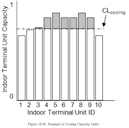
The figure below demonstrates the application of the capacity limit factor for the case where
all indoor terminal units are operating at different capacities. A solution is reached when
the sum of the indoor terminal unit’s cooling capacities (accounting for piping losses) is
equal to the heat pump condenser’s available cooling capacity.

image description

2) The outdoor conditions may limit the amount of cooling the AirConditioner:VariableRefrigerantFlow can provide and the total available cooling capacity is less than the rated cooling capacity. The VRF Heat Pump Part Load Ratio will be 1 when this happens and the VRF Heat Pump Maximum Capacity Cooling Rate and VRF Heat Pump Total Cooling Rate reports will also show the limitation.

3) There is excess cooling load in this zone that sizing did not account for. You said "there is an inline fan (air intake) to the zone", this may be causing the problem. As a test, turn the inline fan off and see if the problem is corrected. If so, this additional load may not be accounted for during sizing which would require that the "cooling factor" be increase more than 1.15.

edit flag offensive delete link more

Comments

Thank you, Sir, for your comprehensive explanation. When I plot the part load ratio, it shows in the hours that the temperature didn't reach the setpoint, the part load ratio is more than 1, this means that the rated cooling load is higher than cooling capacity provided to the zone, it is correct? But I still don't understand why the limitation could happen, and I can't make sure that the outdoor condition is the reason.

I already remove the inline fan to the zone. But the zone temperature still failed to maintain the set-point, although just a little bit decrease than the one shows in Image1

Eru's avatar Eru  ( 2019-11-07 20:05:43 -0600 )edit

Beside that, it is worth to define the air intake with the ZoneVentilation::DesignFlowRate and define the ventilation type as intake? Does the AC sizing take into account the ZoneVentilation?

In my case, the model will have two fresh air sources, each source will be distributed to three zones. There is another worthy method to define fresh air intake? Thank you.

Eru's avatar Eru  ( 2019-11-07 20:11:44 -0600 )edit

If this condition still happens. To avoid undersized AC, should I increase the cooling factor?

Eru's avatar Eru  ( 2019-11-07 20:12:49 -0600 )edit

I think the zone ventilation is included in system sizing so that may not be the problem since you still have the problem when you remove the ventilation. If the PLR = 1 at the time the zone temperature exceeds the set point, the system is fully loaded. Is this system fully autosized? What is the combination ratio (see eio file, first number is cooling combination ratio)?

VRF System Information, AirConditioner:VariableRefrigerantFlow, VRF HEAT PUMP, 1.00000, 1.00000, 0.94587, 1.00000

rraustad's avatar rraustad  ( 2019-11-08 08:07:59 -0600 )edit

When PLR > 1, the indoor unit capacity is greater than the outdoor unit capacity and the outdoor unit over drives the compressor to meet the load. Did you look at the VRF Heat Pump Maximum Capacity Cooling Rate report?

rraustad's avatar rraustad  ( 2019-11-08 09:53:52 -0600 )edit

Your Answer

Please start posting anonymously - your entry will be published after you log in or create a new account.

Add Answer

Training Workshops

Careers

Question Tools

2 followers

Stats

Asked: 2019-11-06 02:17:00 -0600

Seen: 338 times

Last updated: Nov 07 '19