Heated Floor HVAC Setpoint Behaviour


Hello All,
I am working with a ZoneHVAC:LowTemperatureRadiant:VariableFlow for two zone (Bedroom and Kitchen in IDF). The object looks like this.
ZoneHVAC:LowTemperatureRadiant:VariableFlow,
House:Bedroom Heated Floor,                           !- Name
On 24/7,                                              !- Availability Schedule Name
House:Bedroom,                                        !- Zone Name
House:Bedroom Heated Floor Radiant Surface List,      !- Surface Name or Radiant Surface Group Name
0.013,                                                !- Hydronic Tubing Inside Diameter
50,                                                   !- Hydronic Tubing Length
OperativeTemperature,                                 !- Temperature Control Type
HeatingDesignCapacity,                                !- Heating Design Capacity Method
autosize,                                             !- Heating Design Capacity
,                                                     !- Heating Design Capacity Per Floor Area
,                                                   !- Fraction of Autosized Heating Design Capacity
4.1e-05,                                              !- Maximum Hot Water Flow
House:Bedroom Heated Floor Hot Water Inlet Node,      !- Heating Water Inlet Node Name
House:Bedroom Heated Floor Hot Water Outlet Node,     !- Heating Water Outlet Node Name
2,                                                    !- Heating Control Throttling Range
TSetHeat,                                             !- Heating Control Temperature Schedule Name
CoolingDesignCapacity,                                !- Cooling Design Capacity Method
autosize,                                             !- Cooling Design Capacity
,                                                     !- Cooling Design Capacity Per Floor Area
,                                                   !- Fraction of Autosized Cooling Design Capacity
,                                                     !- Maximum Cold Water Flow
,                                                     !- Cooling Water Inlet Node Name
,                                                     !- Cooling Water Outlet Node Name
,                                                     !- Cooling Control Throttling Range
,                                                     !- Cooling Control Temperature Schedule Name
SimpleOff,                                            !- Condensation Control Type
1,                                                    !- Condensation Control Dewpoint Offset
CalculateFromCircuitLength,                           !- Number of Circuits
1;                                                    !- Circuit Length
Here the TSetHeat is an External Schedule that I have from BCVTB. It is fixed at 20degC.
EXTERNALINTERFACE:SCHEDULE,
TSetHeat,                 !- Name
Temperature,              !- Schedule Type Limits Name
20;                       !- Initial Value
Also, I am forcing the Water Mass Flow Rate into the Heated Flow to 0.01 kg/s using another External Interface.
EXTERNALINTERFACE:Actuator,
Water_Mass_Flow_Rate_HOUSE_BEDROOM_HEATED_FLOOR,    !- Name
HOUSE:BEDROOM HEATED FLOOR,                         !- Actuated Component Unique Name
Hydronic Low Temp Radiant,                          !- Actuated Component Type
Water Mass Flow Rate;                               !- Actuated Component Control Type
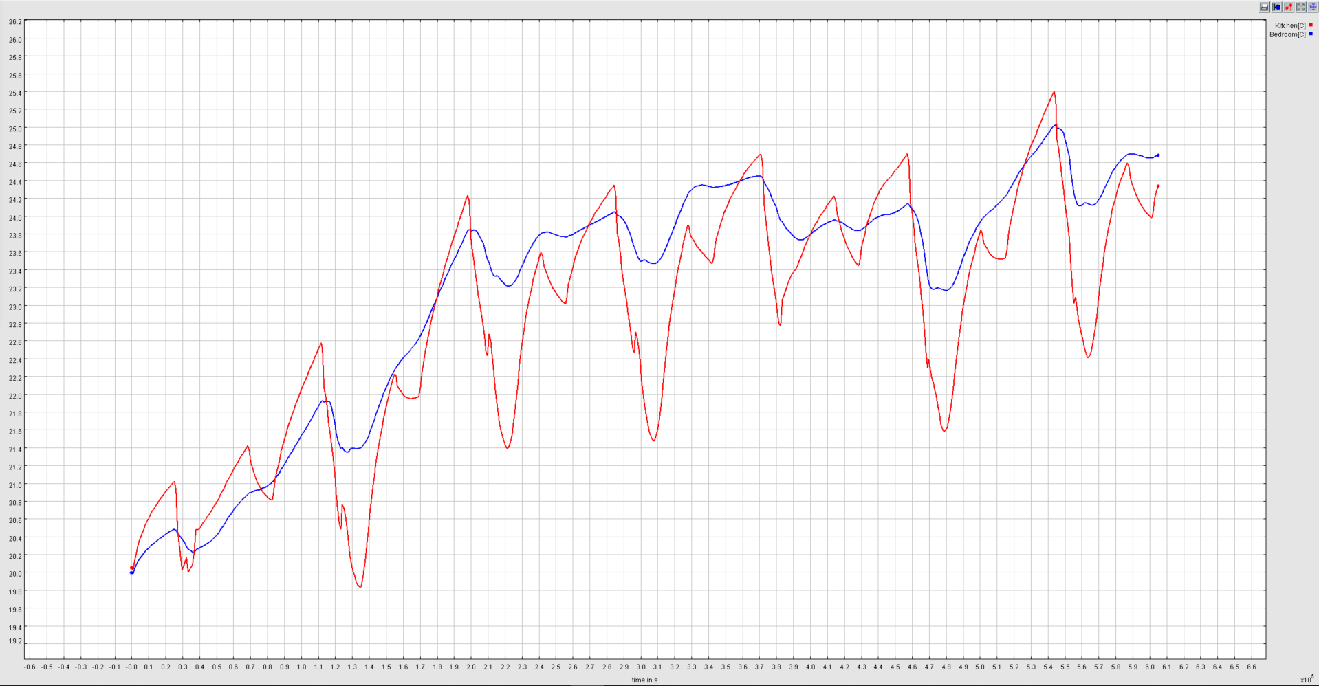
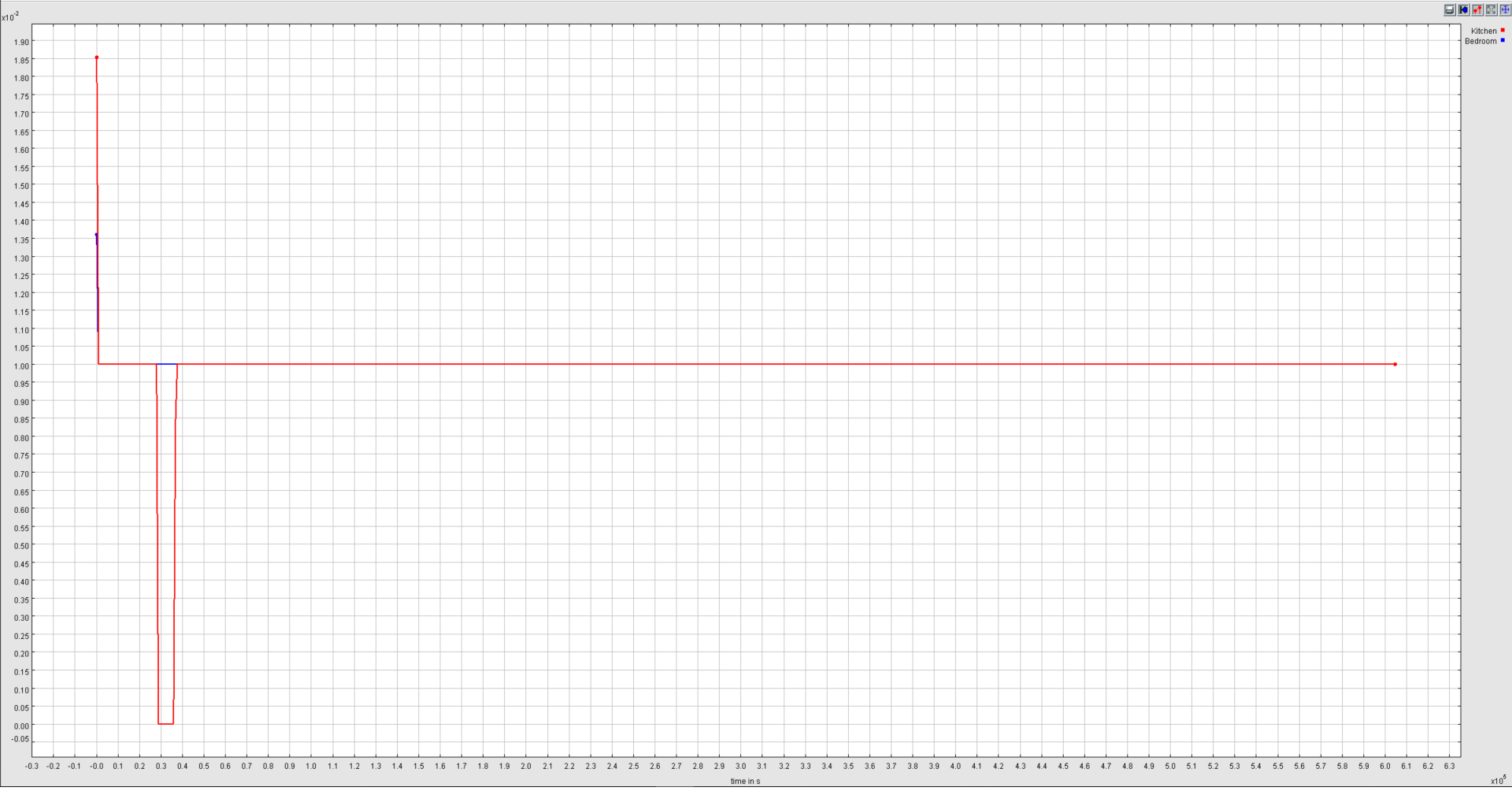
But in the simulation, I do not get either of the Theromstat Setpoint or Mass flow as constat. Below is the plot for the Output Variable Zone Thermostat Heating Setpoint Temperature and Zone Radiant HVAC Mass Flow Rate.
Why is this so? Why they are not constant? How to determine the Setpoint of the Thermostat in this case?
add a comment