Tank source side loop mass flow rate mechanism/ Tank source side control approach
I'm modeling a tankless system to maintain the tank outlet temperature to setpoint (there's no backup heater in the tank model, so the only heat source is the plant loop connected to tank source side), while I didn't find a good approach to achieve a good control either with variable mass flow rate or with variable temperature setpoint, I'm under a strict requirement of running speed for a project so the simulation time step was 1 hour. So please let me know if you guys have any good suggestion of modeling this system or have any insights how the tankless coil is controlled in reality.
I started putting a heat exchanger in the demand loop of boiler and serving heat to the WaterHeater:Mixed source side, in which case the source side mass flow rate and source side inlet temperature were constant all the time, I tried EMS to control the setpoint manager schedule while unfortunately ended up with this question, the results of this approach were not too bad, but it seemed to be something wrong within the node connection and plant simulation.
Then I surprisingly found if I directly connected the tank source side with boiler plant loop as the only component in demand side and set the Pump:VariableSpeed Pump Control Type to Intermittent, the mass flow rate could change trying to meet the loads, which serves my purpose. However, when the boiler is serving both heating coils and tanks, the tank source side mass flow rate changed negligibly. Maybe it's because when the tank was put in parallel with other heating coils, the dhw loads are not significant compared with total heating demand.
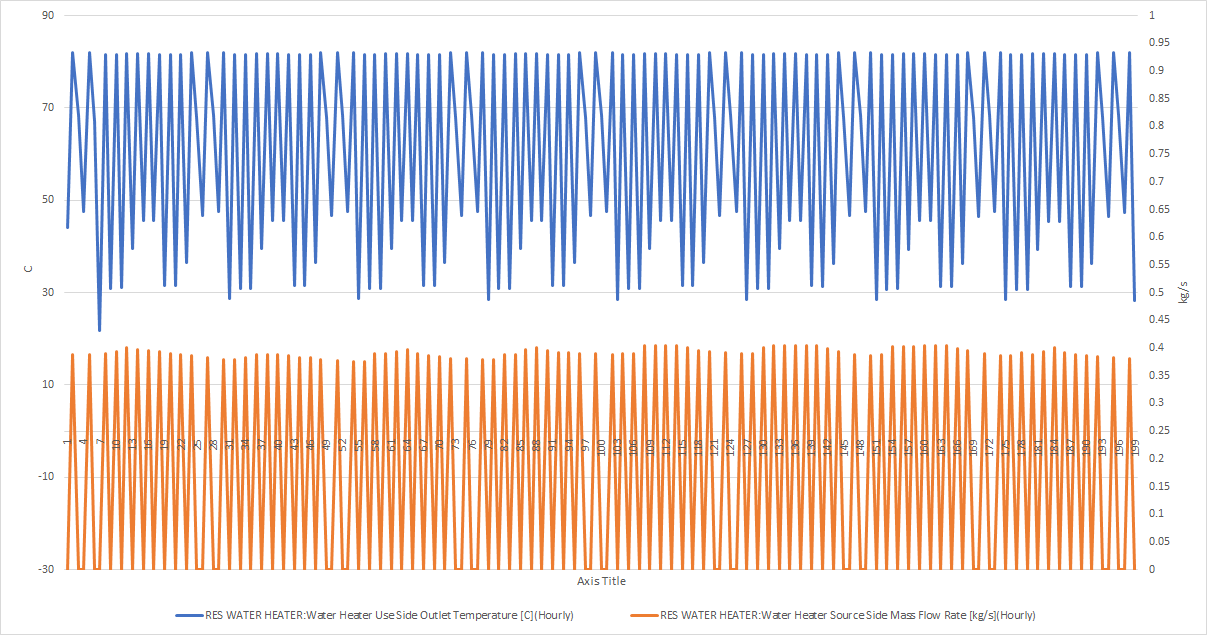
And the results are different between E+ released version and develop version (git "develop" branch), in released 9.1.0, the mass flow rate and tank temperature are plotted as following:

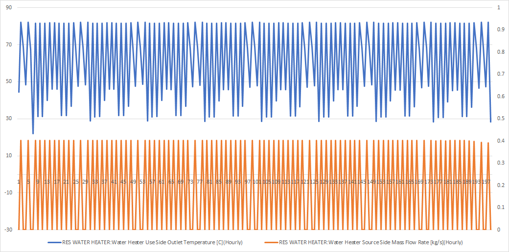
While building in "develop", the plot is:

Their trends are similar but the mass flow rates became more constant in latest "develop" branch. The reason why I have to use the develop codes is that I want to implement the code in bug-fixed branch in my local machine which is synchronized with the latest develop branch. But the results were for the develop branch only without my changes so the impact could be eliminated. My conclusion is that neither of these two is working for me because they are not helping the tank temperature to be controlled at my setpoint (52.6667C).
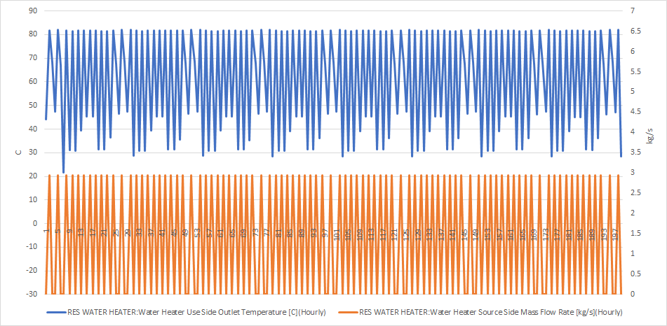
I tried to use my first model where a heat exchanger was put in the boiler loop and supplying heat for tank in another added loop, I removed EMS, and put the same Pump:VariableSpeed with Intermittent mode, I wish in this model the tank source side mass flow rate could be adjusted by dhw loads, but it turned out to be constant.

I am very interested in how E+ models the mass flow rate in tank source side? Why in some cases pumps get ...


Can you elaborate on the need for a 1-hour simulation timestep? That is very atypical in energy modeling applications - usually timesteps are 10-15 minutes.
I think this is largely issue of the problem you constructed. In reality, a 1 gallon indirect tankless just can't be controlled well with high flow rate requests. A simulation timestep of 1 hour isn't going to accurately capture a system that operates on the scale of seconds to minutes (1-2 gpm flow rat for a 1 gallon tank).
We are working on the Home Energy Score project where we intend to promote E+ as a uniform engine (if I understood correctly), so speed is one of the key aspects we need to consider.