Question-and-Answer Resource for the Building Energy Modeling Community
Get started with the Help page
Ask Your Question
2

The cooling load of my facility is 217 kW. The coil load is 636 kW. How can I see the components of the coil load to verify that the sum of the [facility load + other loads] is 636 kW. I would like to know the other components of the coil load

asked 2018-07-22 23:52:56 -0600

Siv's avatar

updated 2018-07-24 01:22:14 -0600

The cooling load of my facility is 217 kW. The coil load is 636 kW. How can I see the components of the coil load to verify that the sum of the [facility load + other loads] is 636 kW. I would like to know the other components of the coil load.
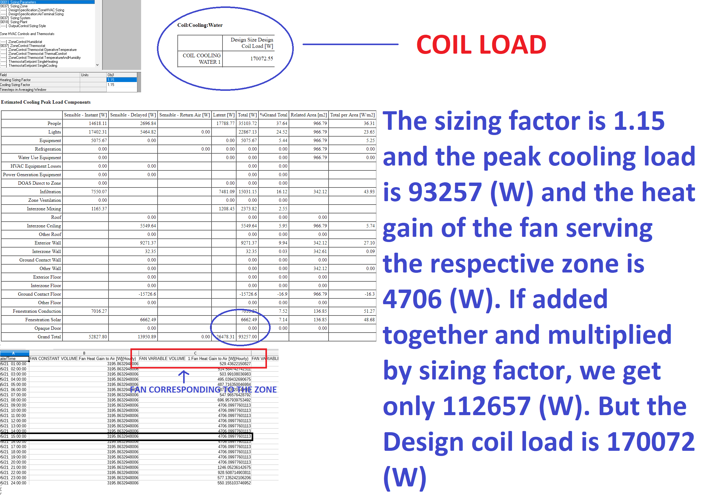
image description

edit retag flag offensive close merge delete

Comments

If I could make a quick suggestion, since I start to see a pattern here: it'd be best if you could find shorter, clearer, post titles in the future! Something like "Cannot recreate total coil load from facility load" here would do for example. Thank you!

Julien Marrec's avatar Julien Marrec  ( 2018-07-24 03:45:33 -0600 )edit
1

Sure thing, I will make sure the titles are shorter from here on.

Siv's avatar Siv  ( 2018-07-24 03:51:01 -0600 )edit

1 Answer

Sort by ยป oldest newest most voted
2

answered 2018-07-23 08:22:44 -0600

(related to similar question here)

  1. The zone sensible loads are shown in the "HVAC Sizing Summary" table output, "Zone Sensible Cooling" and "... Heating" subtables. The sensible loads are used to calculate the zone supply air flow rates using the supply temperatures specified in Sizing:Zone. Any sizing factors in Sizing:Parameters or Sizing:Zone are already applied in the "User" values in this table. Note that the zone "Minimum Outdoor Air Flow Rate" is listed in this subtable, but it is not included yet in the load, these get used later.

  2. The "System Design Air Flow Rates" subtable shows the system air flow rates (which may be coincident or non-coincident depending on the Sizing:System inputs) that are used to size the central system coils.

  3. The "Coil Sizing Summary" subtable shows the entering and leaving conditions used to design the coil. Entering conditions are based on the zone conditions at the time of the system peak mixed with outdoor air. Leaving conditions are from the Sizing:System inputs. The coil sizing also adds in supply fan heat. For cooling coils, the total capacity includes the latent load.

If you want to see the various load components impacting the coil, run a Sizing Period (design day) simulation and use output variables to report the zone sensible load, the zone latent loads, the zone mechanical ventilation loads, and the fan heat.

edit flag offensive delete link more

Comments

I understand, however after running a sizing period simulation I have obtained certain values. The total zone load from the FacilityLoadComponentSummary is 93257 watts, whereas the fan heat gain is 4706 watts When added and multiplied with the sizing factor, I get 112657 watts. But the size of my coil is 17072 watts. And moreover, I am unbale to report zone sensible load, zone latent loads and mechanical ventilation loads using output:variables. I have attached a picture of the results to my question above.

Please help me regarding this.

Siv's avatar Siv  ( 2018-07-24 01:21:34 -0600 )edit

"And moreover, I am unable to report zone sensible load, zone latent loads and mechanical ventilation loads using output:variables". Output:VariableDictionary,idf; will produce an rdd output file with all of the available variables. Copy/paste desired variables from here into your idf and re-run.

MJWitte's avatar MJWitte  ( 2018-07-24 17:45:30 -0600 )edit

I am using the output:variable zone mechanical ventilation cooling load energy and diving it by 3600 to obtain the result in J/s (watts) to obtain the cooling load due to the outside air. I am adding this ventilation load with the fan heat gain to air and the zone grand total load from ZoneComponentLoadSummary and multiplying all the quantities with my sizing factor of 1.15, to my surprise this value in most cases matches the Design Coil Load from Equipment Summary with just an error of 1 or 2 %. Please tell me, if this procedure is alright to recreate the components of the coil load

Siv's avatar Siv  ( 2018-07-25 06:28:39 -0600 )edit

Close, but not exactly. The "Zone Component Load Summary" table grand total is not exact for sensible. Use the "Peak Sensible Load" from the "Cooling Peak Conditions" table, add the latent from the grand total and then multiply by your sizing factor. And don't forget to add supply fan heat.

MJWitte's avatar MJWitte  ( 2018-07-25 14:47:56 -0600 )edit

You see, with respect to my zone, the grand total of the Sensible (Instant + Delayed ) is (52816.36 + 13937.54). The "cooling peak conditions table" gives the same value, however multiplied by my sizing factor. To conclude:

The coil load for a case where only cooling is available can be recreated as follows

[ Zone grand total load + fan heat gain to air + (zone mechanical ventilation cooling load energy/3600) ]*sizingfactor

Please let me know if you find anything amiss.

Siv's avatar Siv  ( 2018-07-25 23:42:46 -0600 )edit

Your Answer

Please start posting anonymously - your entry will be published after you log in or create a new account.

Add Answer

Training Workshops

Careers

Question Tools

1 follower

Stats

Asked: 2018-07-22 23:52:56 -0600

Seen: 542 times

Last updated: Jul 24 '18