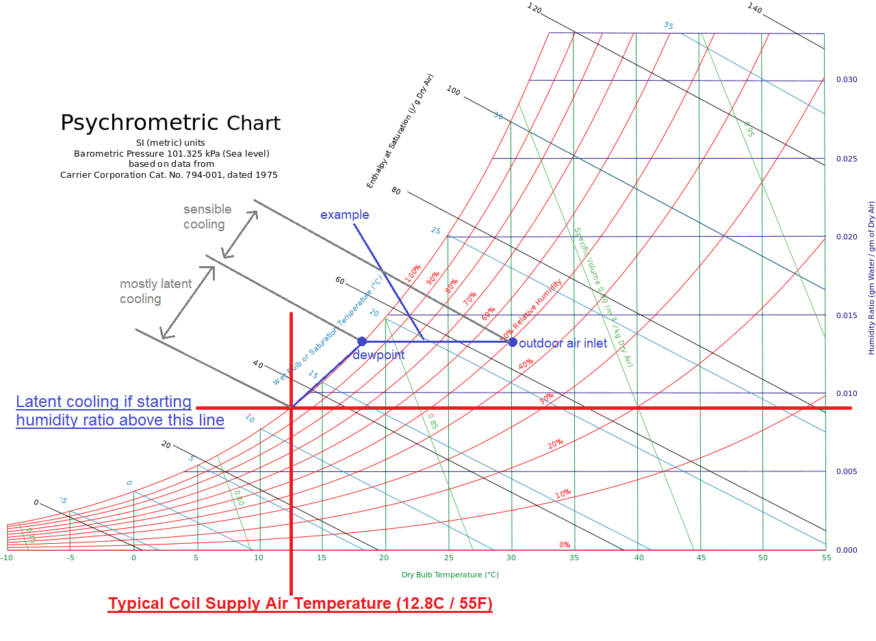
How to control latent cooling energy for CoilSystem:Cooling:DX
I am modelling energy model using CoilSystem:Cooling:DX which is generated by Honeybee using 4.Packaged Single Zone-HP assigned by Assign HVAC system component.
When I investigate result, almost half of the cooling energy treated by cooling coil is latent(39MWh for latent,41MWh for sensible) even though I have not implemented any humidity control using ZoneControl:Humidistat
Since cooling energy is much bigger than I expected and building program is residential which dont control humidity, I want to reduce latent cooling energy. I tried to specify Dehumidification Cotrol Type to None and Run on Sensible Load to yes. However, still cooling energy is same.
Does anyone know what parameter I can change to control latent cooling energy treated by cooling coil?
Also where can I find documentation explaining how they are calculating latent load treated by cooling coil?
CoilSystem:Cooling:DX
CoilSystem:Cooling:DX,
    Coil Cooling DX Single Speed 1 CoilSystem,  !- Name
    Always On Discrete,      !- Availability Schedule Name
    Node 13,                 !- DX Cooling Coil System Inlet Node Name
    Node 14,                 !- DX Cooling Coil System Outlet Node Name
    Node 14,                 !- DX Cooling Coil System Sensor Node Name
    Coil:Cooling:DX:SingleSpeed,  !- Cooling Coil Object Type
    Coil Cooling DX Single Speed 1,  !- Cooling Coil Name
    None,                    !- Dehumidification Control Type
    Yes;                     !- Run on Sensible Load
Coil:Cooling:DX:SingleSpeed
Coil:Cooling:DX:SingleSpeed,
    Coil Cooling DX Single Speed 1,  !- Name
    Always On Discrete,      !- Availability Schedule Name
    Autosize,                !- Gross Rated Total Cooling Capacity {W}
    Autosize,                !- Gross Rated Sensible Heat Ratio
    3,                       !- Gross Rated Cooling COP {W/W}
    Autosize,                !- Rated Air Flow Rate {m3/s}
    773.3,                   !- Rated Evaporator Fan Power Per Volume Flow Rate {W/(m3/s)}
    Node 13,                 !- Air Inlet Node Name
    Node 14,                 !- Air Outlet Node Name
    Curve Biquadratic 1,     !- Total Cooling Capacity Function of Temperature Curve Name
    Curve Quadratic 1,       !- Total Cooling Capacity Function of Flow Fraction Curve Name
    Curve Biquadratic 2,     !- Energy Input Ratio Function of Temperature Curve Name
    Curve Quadratic 2,       !- Energy Input Ratio Function of Flow Fraction Curve Name
    Curve Quadratic 3,       !- Part Load Fraction Correlation Curve Name
    ,                        !- Minimum Outdoor Dry-Bulb Temperature for Compressor Operation {C}
    ,                        !- Nominal Time for Condensate Removal to Begin {s}
    ,                        !- Ratio of Initial Moisture Evaporation Rate and Steady State Latent Capacity {dimensionless}
    ,                        !- Maximum Cycling Rate {cycles/hr}
    ,                        !- Latent Capacity Time Constant {s}
    ,                        !- Condenser Air Inlet Node Name
    AirCooled,               !- Condenser Type
    0,                       !- Evaporative Condenser Effectiveness {dimensionless}
    Autosize,                !- Evaporative Condenser Air Flow Rate {m3/s}
    Autosize,                !- Evaporative Condenser Pump Rated Power Consumption {W}
    0,                       !- Crankcase Heater Capacity {W}
    0,                       !- Maximum Outdoor Dry-Bulb Temperature for Crankcase Heater Operation {C}
    ,                        !- Supply Water Storage Tank Name
    ,                        !- Condensate Collection Water Storage Tank Name
    0,                       !- Basin Heater Capacity {W/K}
    10;                      !- Basin Heater Setpoint Temperature {C}


