Question-and-Answer Resource for the Building Energy Modeling Community
Get started with the Help page
Ask Your Question
6

Why is the boilers.idf condensing boiler curve so linear?

asked 2018-01-30 07:26:50 -0500

dhollman's avatar

updated 2018-03-11 10:58:10 -0500

TLDR: The sample EnergyPlus condensing boiler curve doesn't look like a typical condensing boiler curve. Is there something wrong with it?


Samples for boiler performance curves are available in boilers.idf.

The first curve is for a "Gas-fired condensing boiler...Use curve below for a condensing boiler having a nominal thermal efficiency of 0.89" and consists of:

  Curve:Biquadratic,
    CondensingBoilerEff,     !- Name
    1.124970374,             !- Coefficient1 Constant
    0.014963852,             !- Coefficient2 x
    -0.02599835,             !- Coefficient3 x**2
    0.0,                     !- Coefficient4 y
    -1.40464E-6,             !- Coefficient5 y**2
    -0.00153624,             !- Coefficient6 x*y
    0.1,                     !- Minimum Value of x
    1.0,                     !- Maximum Value of x
    30.0,                    !- Minimum Value of y
    85.0;                    !- Maximum Value of y

In order to interpret this I looked in the EnergyPlus Input/Output Reference, section Boiler:HotWater, subsection Field: Normalized Boiler Efficiency Curve Name which indicates:

For all curve types PLR is always the x independent variable. When using 2 independent variables, the boiler outlet water temperature (Toutlet) is always the y independent variable.

Based on that I plotted several curves, expecting to see a more-or-less typical curve for a condensing boiler which would have an inflection around ~120 F. Like this one:

image description

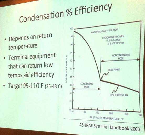
(from http://www.greenbuildingadvisor.com/b... )

But instead it looks like this:

image description

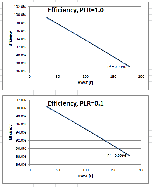
The trendlines are almost exactly linear. I don't think I've made an error plotting the curve, and you can see just from inspecting the coefficients that for a PLR held constant the supply temperature terms are quite small, especially the quadratic one.

Does this data really represent a condensing boiler?

edit retag flag offensive close merge delete

3 Answers

Sort by ยป oldest newest most voted
0

answered 2018-01-30 08:51:51 -0500

updated 2018-01-30 08:52:20 -0500

Linearity is your friend. Complex performance curves often lead to unsteady and slower simulations.

edit flag offensive delete link more

Comments

1

I don't think I understand your point... I don't want to do the wrong thing quickly :)

dhollman's avatar dhollman  ( 2018-01-30 08:53:28 -0500 )edit

Non linear behaving equations are difficult to solve, they required smaller time-steps to solve and often a solution is not found. If you also include an algebraic condition (like a dew point condition) the problems to solve will raise.

In my humble opinion, your graphs and the picture are similar enough and within the expected certainty of a building simulation. You can be sure that there will be large differences between the simulation model and the real building, but they will be due to other causes.

mapascual's avatar mapascual  ( 2018-01-30 09:18:35 -0500 )edit
1

If someone was specifically trying to assess condensing vs. non-condensing performance this would be a showstopper. (That type of analysis is not uncommon). While they might reach a conclusion similar to your assumption (that it won't matter) the EnergyPlus example curve precludes even doing that. And in what seems to be a confusing / misleading way (to me).

dhollman's avatar dhollman  ( 2018-01-30 09:21:43 -0500 )edit

I don't agree. Low temp, non condensing boilers should use a performance curve independent of the water return temperature.

mapascual's avatar mapascual  ( 2018-01-30 09:32:02 -0500 )edit

But the question is about the condensing boiler curve.

dhollman's avatar dhollman  ( 2018-01-30 09:45:29 -0500 )edit
2

answered 2018-01-30 10:43:03 -0500

If I recall correctly, those boiler curves came from this document and the two upper curves in Fig. 9 on page 8 are the ones in question. Those curves already account for the return water temperature.

edit flag offensive delete link more

Comments

Okay, so for curve B the parameters were for outdoor reset were (I infer maybe incorrectly) HW supply temperature 75 C at design and 60 C at minimum. The curve in boilers.idf is OK up to 85 C however. Maybe the temps in the PDF are for the return?

In any case, I wonder how typical that chart really is. It says "Standard efficiency levels for various boiler designs" so its not a single physical unit. Plenty of data out there for individual units don't look so linear - eg http://www.lochinvar.com/_linefiles/K... as one example.

dhollman's avatar dhollman  ( 2018-01-30 11:11:26 -0500 )edit

I assumed the 40/30C and 75/60C referred to the leaving/entering water temp of the boiler. As the water temps increase boiler efficiency drops. FYI: I'm no expert on boilers.

rraustad's avatar rraustad  ( 2018-01-30 11:19:23 -0500 )edit
1

Also, you should be able to use a table lookup, Table:TwoIndependentVariables, for the ASHRAE Handbook performance curve to better represent the knee in the curve.

rraustad's avatar rraustad  ( 2018-01-30 12:44:31 -0500 )edit
4

answered 2018-02-02 00:08:18 -0500

Molly Curtz's avatar

updated 2018-02-02 00:19:42 -0500

Please note that the boilers.idf document you linked to clearly states: "For the curve below, specify EnteringBoiler for the Efficiency Curve Temperature Evaluation Variable". According to that, the second independent variable is return water temp, not supply water temp, for this boiler performance curve.

I agree with you that it would be really helpful for the boilers.idf example file to be improved, as I think that's where new comers would tend to look for an initial starting point.(I did this myself, as you have done, and found the curve data to be difficult to justify. Now that I understand from @rraustad the source of these data, it seems understandably not that great. It is not clear what the "part load efficiency [%]" values in the Viessmann Fig. 9 graph represent - they exceed 100% for many conditions.)

As you note, data is available for plenty of actual units, so you will be better off if you create your own curve.

Bear in mind as you are creating a performance curve: consider the range of independent variables that will occur in the simulation. Unless your RWTs will span between 240F and 40F, you do not necessarily have to encompass the entire range of the ASHRAE handbook diagram in order get good results for a particular simulation.

edit flag offensive delete link more

Your Answer

Please start posting anonymously - your entry will be published after you log in or create a new account.

Add Answer

Careers

Question Tools

3 followers

Stats

Asked: 2018-01-30 07:26:50 -0500

Seen: 1,104 times

Last updated: Feb 02 '18