Question-and-Answer Resource for the Building Energy Modeling Community
Get started with the Help page
Ask Your Question
3

Chiller Plant Model

asked 2017-12-07 17:29:34 -0500

Draza's avatar

updated 2017-12-08 11:28:25 -0500

Hello,

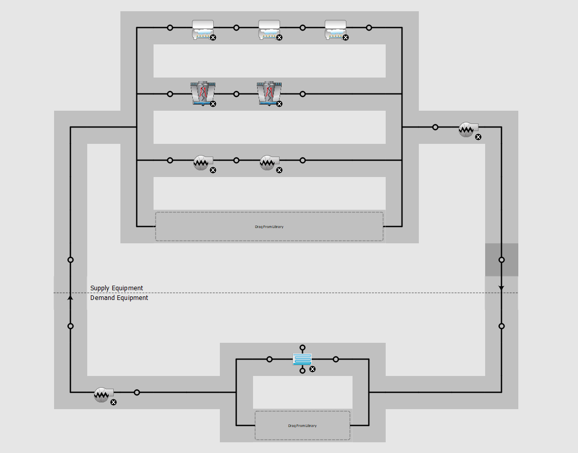
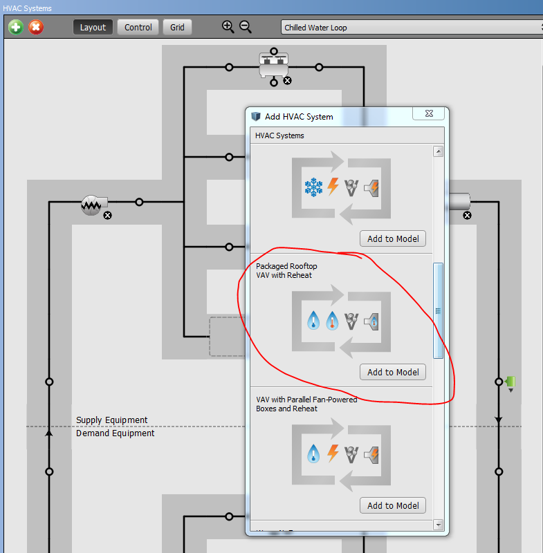
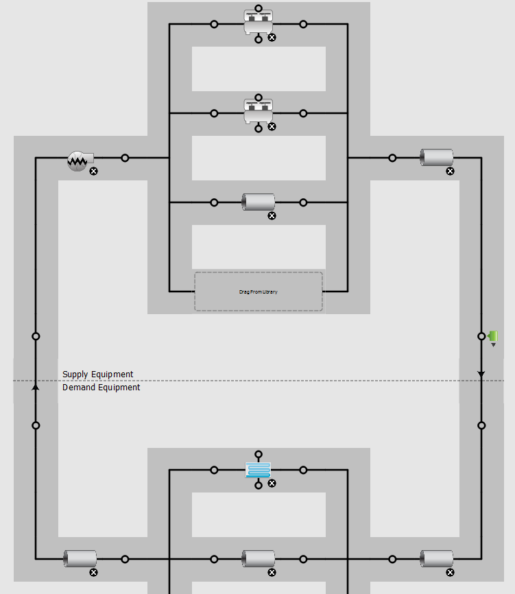
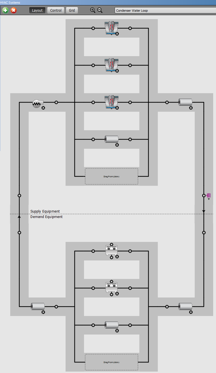
I'm trying to model a chiller plant (two cooling towers, three chillers ((staged)) and multiple pumps) that serves multiple buildings. I am doing a trial run for one building, but am having trouble coming up with the best way to tackle modeling the system. I am using SketchUp/openstudio.

My first instinct was to build the plant, which I will replicate into a model for each building, then attach the "demand side" system on a building and zone level. Is this the best way to go about this type of model? if so I am a little confused as to what components (besides those mentioned above) are mandatory for the model to run? I am also a confused as to which node to place the components on. example: should all three chillers go on the same line on nodes that are horizontal to one another or on separate lines that are vertical from one another? image description

edit retag flag offensive close merge delete

Comments

What software are you using? Please edit the question to include this.

Anna Osborne Brannon's avatar Anna Osborne Brannon  ( 2017-12-07 17:49:21 -0500 )edit

I am using SketchUp/ Openstudio. I have made the edit to the question. Thanks!

Draza's avatar Draza  ( 2017-12-07 17:53:23 -0500 )edit

2 Answers

Sort by ยป oldest newest most voted
3

answered 2017-12-07 18:01:46 -0500

A common approach to modeling central plants is to do your building-level modeling in separate models, then output the hourly cooling loads to individual profiles that are fed into a separate central plant model. These cooling load profiles can be added to secondary chilled water loops that represent each building in the central plant model. The downside to this approach is that the building model and the plant model are not connected, so any changes to the building model means that you have to update the profiles that are being fed into the plant model, though this is pretty easy to do and does not pose a significant inconvenience.

As to whether your chillers should be connected in parallel (what I assume you mean by "horizontal") or series (what I assume you mean by "vertical"), I can say that most chiller plants will have chillers connected in parallel, so that they can be staged on and off depending on the load, and can include a low-load chiller. However, I have heard that series configurations can be very efficient in some applications and increase the available chiller capacity. If you wan to go with a "typical" configuration, though, use parallel.

edit flag offensive delete link more

Comments

Anna, thanks for the information. This is helpful.

As for the chiller connections, I was referring to the node placement within the "HVAC Systems" tab of open studio. The software does make some decisions for you by arranging the equipment but the placement isn't always the same. I have attached a screen shot of the layout that I have currently to the original question.

Draza's avatar Draza  ( 2017-12-08 11:27:42 -0500 )edit

I agree 100% with Anna's load profile comments. I have used this approach recently to show that serial chillers can indeed be more efficient than parallel chillers (within the limitations of EnergyPlus' Chiller:Electric:EIR model).

On the screenshot of the plant you attached, I must say, I have never seen this arrangement before, Normally, the chillers are put in one plant loop (Loop Type Cooling), and the cooling towers are put in another plant loop (Loop Type Condenser). Also, it seems yo have too many pumps, some of which may in fact bypass chillers and towers altogether.

Matt Koch's avatar Matt Koch  ( 2017-12-08 12:35:49 -0500 )edit

If I were to rearrange the loops to match your description, would the cooling towers be on the supply side in one loop and the chillers on the demand side, then in the second loop the chillers on the supply side and the cooling coil on the demand side? or would they be completely separated? I am still a little confused as to how the hierarchy of the system structure works in open studio.

Draza's avatar Draza  ( 2017-12-08 12:47:00 -0500 )edit

You got it. The Condenser loop has the towers on the supply side and the chillers on the demand side. The Cooling loop has the chillers on the supply side and the cooling coils on the demand side. The condenser pump is typically on the outlet side of the towers, the cooling pump is typically on the inlet side of the chillers, But there are never pumps in parallel with the towers or chillers.

Matt Koch's avatar Matt Koch  ( 2017-12-08 12:55:04 -0500 )edit

This makes sense. Thanks for the assistance!

Draza's avatar Draza  ( 2017-12-08 13:01:16 -0500 )edit
2

answered 2017-12-08 15:19:23 -0500

updated 2017-12-08 15:20:35 -0500

If you are modeling multiple large buildings, I would suggest making the building models individually and using the district heating and cooling objects to get the plant load for each one.

Often engineers will use a separate software to model the plant to be able to better capture system operation and control. You can also refer to the engineering documentation for EnergyPlus and implement the same chiller and cooling tower logic in a spreadsheet with known loads and weather data. I would recommend this approach if you have many large buildings.

However, if you have many small buildings all part of the same project, it is possible to model this directly in the OpenStudio. If you use this approach, I recommend reading the OpenStudio tutorial on creating HVAC system plant loops to get an idea of how your setup should look.

You can see an example of this by adding a template system from the HVAC systems tab:

image description

Your system will look something like this:

image description

Chilled water loop - you have chillers on the supply side and cooling coils on the demand side. The little circle icons above and below the chiller indicate that it is attached to another loop (the condenser loop). Clicking the circle will bring you to the condenser loop:

image description

On the condenser loop, your chillers are on the demand side and cooling towers on the supply side.

If you want to control the sequence of the chillers and cooling towers in a specific way, you need to specify that in your model. See these recent questions on the forum: Sequential load distribution scheme seems not working and Optimal operation of plant chillers (EnergyPlus).

edit flag offensive delete link more

Comments

Thanks for the clear and thorough response! If I model each building served by the central plant individually using district heating and cooling as a "place holder" will I be able to combine the models into one and add the central plant and remove the district heating and cooling once all the models are finished and working properly.

Draza's avatar Draza  ( 2017-12-08 16:30:34 -0500 )edit

No. You could combine the geometries, but you would need to remake the HVAC systems. Whether you split them depends on your use case. I've modeled several buildings together when all I was doing was looking at glazing options vs. plant size. For other projects doing central plant design with different ages of existing buildings and new buildings, I've modeled the plant separately.

mdahlhausen's avatar mdahlhausen  ( 2017-12-08 16:56:15 -0500 )edit

Your Answer

Please start posting anonymously - your entry will be published after you log in or create a new account.

Add Answer

Careers

Question Tools

3 followers

Stats

Asked: 2017-12-07 17:29:34 -0500

Seen: 194,669 times

Last updated: Dec 08 '17