Question-and-Answer Resource for the Building Energy Modeling Community
Get started with the Help page
Ask Your Question
1

ASHP tank not providing heat to storage plant loop

asked 2015-02-04 09:12:10 -0500

updated 2017-05-17 12:44:19 -0500

I have two IDFs which are substantially the same. They each have a primary HW loop, a PCM storage loop (two tanks in series) a secondary HW loop (baseboards and DHW). However one has a WaterHeater:HeatPump on the primary loop while the other has a Boiler:HotWater. The ASHP doesn't provide any heat to the PCM storage loop, while the gas boiler does. The PCM storage loop does provide heat to the secondary HW loop though since the tank temperature drops and the zones receive heat at the start of the run period (and I've checked the mass flow rate).

I have setpoint managers referencing set-points at the output node of each supply half-loop but it seems that one of the ones on the PCM loop is not working correctly when the ASHP is present. The ASHP gets up to temperature but doesn't provide any heat.

Here are a few charts which might help identify what's wrong.

image description

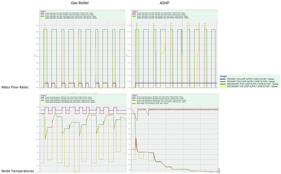
As I read them, the ASHP tank temperature (the unlabelled line in the bottom right chart) is staying high but no heat is ever drawn from it, meaning that all the other nodes lose heat which is not replaced. I've checked and the mass flow rate from the ASHP WaterHeater:Mixed tank is zero at all times while the other tanks all provide flow when there is heat demand from the zones. Why would this be happening?

edit retag flag offensive close merge delete

2 Answers

Sort by ยป oldest newest most voted
2

answered 2015-02-05 06:00:23 -0500

updated 2015-02-05 06:07:05 -0500

@Archmage's answer is somewhat along the right lines in that the heat pump tank wasn't providing any flow, and also that there is a difference in how water heaters operate when the use side is connected to a plant loop. But it wasn't down to a lack of demand. The IDF already had HeatExchanger:FluidToFluid objects set to UncontrolledOn so that part of the demand was already there. That can be seen by the mass flow rate of the Primary HW Loop Supply Side Outlet.

The problem was that I was missing a Use Side Design Flow Rate field on the water heater that forms part of the WaterHeater:HeatPump. From the mixed water heater docs:

Field: Use Side Design Flow Rate

This field is optional and is used to specify the design flow rate through the Use Side of the water heater. The volumetric design flow rate is specified in m3/s. The field is needed when the Use Side is connected to a plant loop. The field can be autosized. If autosized, then the input file should include a Plant Sizing object for the plant loop. Sizing results are reported in the EIO file.

The key part being "The field is needed when the Use Side is connected to a plant loop." This is an optional field, the water heater I was using as a template didn't have one. It wasn't till I went back through the example file HeatPumpWaterHeater.idf that the difference became apparent.

edit flag offensive delete link more
3

answered 2015-02-04 11:29:51 -0500

Archmage's avatar

The difference between a water heater and boiler is that only the boiler is setup to respond to plant operation schemes that dispatch load to the supply machines. The water heater's use side is basically passive, flow needs to be pushed through it by other things. I would look into how the primary HW loop is controlled and I imagine there would need to be some considerable differences between the two cases. I find that when you have tanks on the supply side of a complex plant, it is helpful to use a fluid HX on the demand side to control flow through the tanks.

edit flag offensive delete link more

Your Answer

Please start posting anonymously - your entry will be published after you log in or create a new account.

Add Answer

Careers

Question Tools

1 follower

Stats

Asked: 2015-02-04 09:12:10 -0500

Seen: 433 times

Last updated: Feb 05 '15