Cooling Load for Interzone Wall negative?


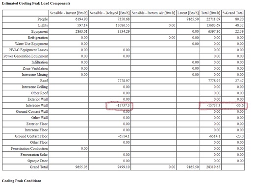
I noticed that the auto-sized air flow of my VAV system is much lower that the design air flow in the actual design. The Estimated Cooling Peak Load Components appear to be ok, with one exception. Almost each space in the model has a relatively large “negative” Interzone Wall cooling load component. My understanding is that Interzone Wall should reflect heat transfer between the two adjacent zones, but I’m not sure how it is calculated by E+.
This is a typical office building. All the spaces use the same Thermosta Setpoint:DualSetpoint and identical occupancy/ lighting/ equipment /HVAC system schedules. There are a few unconditioned spaces in the model, but none of them is adjacent to the spaces that I’m analyzing.
I try to change Outside Boundary Conditions from Surface to Adiabatic for all the interior walls for several zones, but that didn’t have much impact on their cooling loads. I was able to get read of a "negative" Ground Contact Floor component by changing Ground to Adiabatic though.
Can someone provide explanation why an Interzone Wall load component would be so large and “negative”?!


An adiabatic wall will not "transfer heat out of the zone, but will store heat in thermal mass". Are your interzone walls set to 'Air Walls' (are you using OpenStudio?)
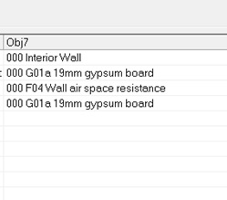
The model geometry was generated in OpenStudio. Construction of interior walls in E+ is : 19mm gypsum board, Wall air space resistance (R-1.2), 19 mm gypsum board. Interzone wall cooling load component is 25% of the total cooling load or greater for most of the zones.
Is this the zone level cooling peak? What date/time of day does it occur and what is the geography? Do all peaks for all zones occur at the same time? If peaks are not occuring at the same time, you might be getting heat transfer to surrounding, cooler zones. Just a thought...
For this particular zone, the zone level cooling peak occurs at 15:00 pm. The cooling peak does not occur at the same time for all zones and takes place between 11:00 am and 16:00 pm. The location is in climate zone 4A, Georgia. The reason I'm looking at these loads is because my auto-sized air flow for the system is very low and it appears to be calculated using the cooling load from this table. I don't understand why I would have the cooling load components between the zones that have the same set-point temperatures. Thanks for sharing your thoughts.
Zone temperature setpoint != zone temperature; you could check zone temperatures to confirm all adjacent zones are same temperature at time of peak.
The only other thing I can think of is your boundary condition is not specified correctly, but you said you reviewed that. In my mind, the only item that impacts heat transfer across interior walls is difference in temperature.