Question-and-Answer Resource for the Building Energy Modeling Community
Get started with the Help page
Ask Your Question
3

Designbuilder/EnergyPlus Relief fan

asked 2017-08-11 07:58:01 -0500

kbk78's avatar

updated 2017-08-11 07:58:44 -0500

How do I setup a relief fan on the AHU in designbuilder or energyplus. The fan would need to track the outdoor air flow including increased outdoor airflow during economizer mode.

edit retag flag offensive close merge delete

2 Answers

Sort by » oldest newest most voted
3

answered 2018-07-16 16:53:31 -0500

Molly Curtz's avatar

updated 2018-07-16 16:54:40 -0500

I found your question because I have the same one. In Energy Plus, I was able to add a relief fan as a component on the AirLoopHVAC:OutdoorAirSystem, just by modifying the AirloopHVAC:OutdoorAirSystem:EquipmentList and adding the Relief fan object. I started with the expanded IDF from the example file "HVACTemplate-5ZoneVAVWaterCooled.idf". I checked the hourly output variables for the fan power and the node flow exiting the fan and it seems to work. Here are the objects I modified/added:

 AirLoopHVAC:OutdoorAirSystem:EquipmentList,
   VAV Sys 1 OA System Equipment,                           !- Name
   OutdoorAir:Mixer,                                        !- Component Object Type
   VAV Sys 1 OA Mixing Box,                                 !- Component Name
   Fan:VariableVolume,                                        !- Component Object Type
   VAV Sys 1 Relief Fan;                                 !- Component Name

 Fan:VariableVolume,
   VAV Sys 1 Relief Fan,                                    !- Name
   FanAvailSched,                                           !- Availability Schedule Name
   0.7,                                                     !- Fan Efficiency
   600,                                                     !- Pressure Rise {Pa}
   autosize,                                                !- Maximum Flow Rate {m3/s}
   Fraction,                                                !- Fan Power Minimum Flow Rate Input Method
   0.25,                                                    !- Fan Power Minimum Flow Fraction
   ,                                                        !- Fan Power Minimum Air Flow Rate {m3/s}
   0.9,                                                     !- Motor Efficiency
   1,                                                       !- Motor in Airstream Fraction
   0.35071223,                                              !- Fan Power Coefficient 1
   0.30850535,                                              !- Fan Power Coefficient 2
   -0.54137364,                                             !- Fan Power Coefficient 3
   0.87198823,                                              !- Fan Power Coefficient 4
   0,                                                       !- Fan Power Coefficient 5
   VAV Sys 1 Relief Air Outlet,                           !- Air Inlet Node Name
   VAV Sys 1 Relief Fan Outlet;                             !- Air Outlet Node Name
edit flag offensive delete link more

Comments

Dear Molly, Is this case something you could share? I have the same question and would be happy to have a working example!

Maria Alonso's avatar Maria Alonso  ( 2022-05-24 01:43:17 -0500 )edit
2

answered 2017-08-16 14:15:38 -0500

Hi @kbk78

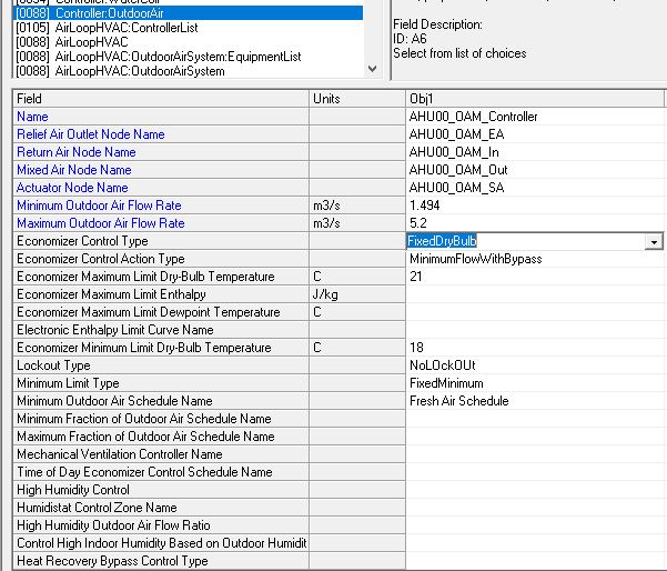
Not sure if you figured this out already. In EnergyPlus, the outdoor airflow is controlled using the object Controller:OutdoorAir . Based on how you want to model the economizer, you can look for the appropriate selection using the E+ I/O ref guide. You can then model the limits according to your system control sequence of operations.

This controller is applied to AirLoopHVAC using a AirLoopHVAC:ControllerList.

image description

Hope that answers your question!

  • Raghu
edit flag offensive delete link more

Comments

@Raghu, question is about modeling a relief fan not about modeling economizer. The return fan on the AHU moves the return air from the zone to the AHU. But the relief fan exhausts the excess air (that was brought in as outside air) from the return air to the outside to keep the airflow in balance. Though we can include a zone exhaust fan it does not pass through the AHU heat recovery coil and also the exhaust would not increase if the AHU is in economizer mode.

kbk78's avatar kbk78  ( 2017-08-16 15:43:28 -0500 )edit

Could you explain the system that you are trying to model and how you intend to control it?

rsunnam's avatar rsunnam  ( 2017-08-16 15:49:46 -0500 )edit

Hello @rsunnam ! I am trying to model a system similar to the one mentioned here. The only difference is that I am trying to model a hvac system that operates with 100% OA when outdoor is both below 23ºC DBT and 80% RH. Also, when outdoor air temperature does not met this criteria, hvac system turns on a cooling coil to maintain the room at 25ºC DBT.

I have tryied a bunch of diferent configuration on air loops and I could not properly represent this system.

The thing is that I can not tell the program to measure both DBT and RH OA and just let the OA in the thermal zone if it is bellow specs

lrebello's avatar lrebello  ( 2023-07-31 16:58:57 -0500 )edit

Your Answer

Please start posting anonymously - your entry will be published after you log in or create a new account.

Add Answer

Careers

Question Tools

1 follower

Stats

Asked: 2017-08-11 07:58:01 -0500

Seen: 886 times

Last updated: Jul 16 '18