Question-and-Answer Resource for the Building Energy Modeling Community
Get started with the Help page
Ask Your Question
3

How can we model ASHRAE 90.1-2004 Compliant Chilled/Condensing Water Loop Pumps?

asked 2017-06-21 15:14:00 -0500

SAndo's avatar

updated 2017-06-23 08:14:04 -0500

Please scroll down to review the sections from ASHRAE 90.1-2004 Appendix G regarding modeling of chilled/condensing water loop pumps. Below are our 2 questions:

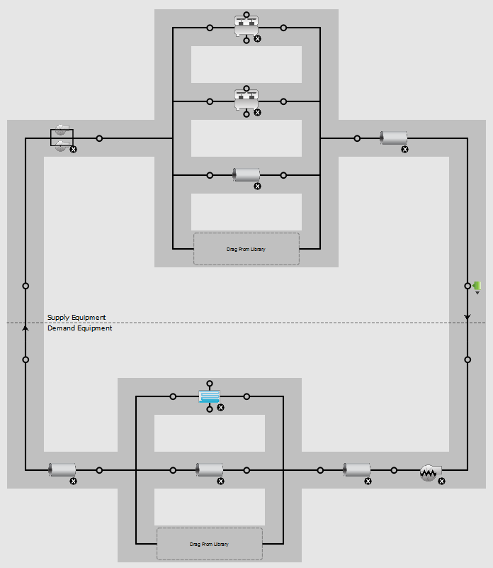
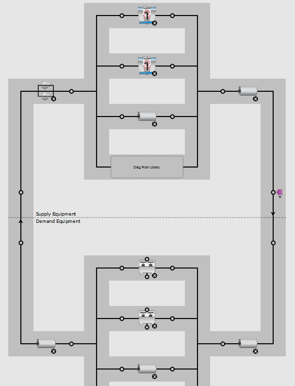
  1. To model chilled/condensing water loop pumps in compliance with ASHRAE 90.1-2004, should we be modeling pump per chiller configuration both for the chilled water and condensing water loop? Or, should we use headered pumps (each with as many pumps as chillers) both for the chilled water and condensing water loop?

  2. Appendix G says none of the chillers should exceed 800 tons in the baselines. In very large projects, we end up calculating more than 10 chillers per loop when we assume maximum of 800 tons each. Yet, EnergyPlus does not allow for more than 10 chillers per loop. What should we do in these cases? Should we divide the building into multiple chilled water loops so that each loop has a max of 10 x 800 tons = 8000 tons? Or, should we model the whole building with a single chilled water loop with 10 chillers even if we end up exceeding 800 tons in each chiller?


Relevant sections from ASHRAE 90.1-2004 Appendix G:

G3.1.3.7 Type and Number of Chillers (Systems 7 and 8)… The baseline building design’s chiller plant shall be modeled with chillers having the number and type as indicated in Table G3.1.3.7 as a function of building conditioned floor area. Building- Conditioned Floor Area Number and Type of Chiller(s)

  • ≤120,000 ft2 1 screw chiller
  • >120,000 ft2, <240,000 ft2 2 screw chillers sized equally
  • ≥240,000 ft2 2 centrifugal chillers minimum with chillers added so that no chiller is larger than 800 tons, all sized equally

G3.1.3.10 Chilled Water Pumps (Systems 7 and 8). The baseline building design pump power shall be 22 W/gpm. Chilled water systems serving 120,000 ft2 or more shall be modeled as primary/secondary systems with variable-speed drives on the secondary pumping loop. Chilled water pumps in systems serving less than 120,000ft2 shall be modeled as a primary/secondary systems with secondary pump riding the pump curve.

G3.1.3.11 Heat Rejection (Systems 7 and 8)…. The baseline building design condenser water pump power shall be 19 W/gpm. Each chiller shall be modeled with separate condenser water and chilled water pumps interlocked to operate with the associated chiller.

edit retag flag offensive close merge delete

1 Answer

Sort by » oldest newest most voted
1

answered 2017-06-28 13:37:30 -0500

updated 2017-06-28 13:48:41 -0500

The most straightforward approach of putting a Pump:ConstantSpeed on each branch in front of each Chiller:Electric:EIR, putting a Pump:VariableSpeed on the demand inlet, and using 'CommonPipe' does not work because of a bug in EnergyPlus that keeps the branch pumps running even when no flow is required.

I believe that the alternative modeling approach below meets the requirements of 90.1 Appendix G when the baseline model has more than 1 chiller while avoiding the EnergyPlus bug.

This approach works because the chillers and cooling towers are all sized equally, and therefore the pump staging matches their operation. If you had different sized chillers, you would need to use a more complex approach and model the primary side and secondary side as two separate PlantLoops connected by a HeatExchangerFluidToFluid, model a separate condenser water loop for each cooling tower, and review the timeseries data to ensure things were working as intended.

Chilled water loop:

  • PlantLoop
    • Branch for each chiller
    • Chiller 'Sizing Factor' = 1/number of chillers (if autosizing chillers) for all chillers
    • 'Common Pipe Simuation' = 'CommonPipe' (found by clicking dotted line in center of PlantLoop)
    • 'Load Distribution Scheme' = 'SequentialLoad'
  • HeaderedPumps:ConstantSpeed on Supply Inlet Node as constant primary pump per chiller
    • 'Pump Control Type' = 'Intermittent'
    • 'Number of Pumps in Bank' = number of chillers
  • Pump:VariableSpeed on Demand Inlet Node as variable secondary pump
    • 'Pump Control Type' = 'Intermittent'
    • Pump coefficients set to represent required pump control type

image description

Condenser water loop:

  • PlantLoop
    • Branch for each cooling tower
    • Cooling tower 'Sizing Factor' = 1/number of cooling towers (if autosizing cooling towers) for all towers
    • 'Load Distribution Scheme' = 'SequentialLoad'
  • HeaderedPumps:ConstantSpeed on Supply Inlet Node as constant pump per cooling tower
    • 'Pump Control Type' = 'Intermittent'
    • 'Number of Pumps in Bank' = number of cooling towers

image description

Measure code

Here are links to the openstudio-standards code that implements the approach described above:

edit flag offensive delete link more

Your Answer

Please start posting anonymously - your entry will be published after you log in or create a new account.

Add Answer

Careers

Question Tools

4 followers

Stats

Asked: 2017-06-21 15:14:00 -0500

Seen: 731 times

Last updated: Jun 28 '17