OS imports gbXML with reversed floor construction


After import a gbXML file from Revit I see that floor constructions are in reversed order. The file is attached.
First time here? Check out the Help page!
After import a gbXML file from Revit I see that floor constructions are in reversed order. The file is attached.
I finally had a chance to look at this. @macumber may have more information but I think the issue here is that the order of the two adjacent spaces. I think the surfaces goes onto what is listed first as it is, and then is reversed to go into the second space list. OpenStudio may then be re-assigning surface type based on the surface normal it sees. If you fix the surface normals, every thing comes in fine.
Other floor surfaces that didn't exhibit this issue also had a tilt of 180 degrees, and had the same order of the first three points. What was different in this case is that the first adjacent space listed "aim0154" is space for which this is a ceiling and not a floor. When I re-ordered the twp spaces and re-imported the gbxml it was not reversed. Changing the "Tilt" or "SurfaceType" in the gbxml didn't fix it, but I expect we look surface geometry and not the "Tilt" field to determine orientation.
<Surface surfaceType="InteriorFloor" constructionIdRef="aim3637" id="aim4439">
<AdjacentSpaceId spaceIdRef="aim0154" />
<AdjacentSpaceId spaceIdRef="aim3186" />
<RectangularGeometry id="aim4440">
<Azimuth>0</Azimuth>
<CartesianPoint>
<Coordinate>4.619704</Coordinate>
<Coordinate>27.77548</Coordinate>
<Coordinate>121.035</Coordinate>
</CartesianPoint>
<Tilt>180</Tilt>
<Width>23.2687435150146</Width>
<Height>8.42329883575439</Height>
</RectangularGeometry>
<PlanarGeometry>
<PolyLoop>
<CartesianPoint>
<Coordinate>-10.09667</Coordinate>
<Coordinate>31.64708</Coordinate>
<Coordinate>121.035</Coordinate>
</CartesianPoint>
<CartesianPoint>
<Coordinate>-5.850338</Coordinate>
<Coordinate>37.99228</Coordinate>
<Coordinate>121.035</Coordinate>
</CartesianPoint>
<CartesianPoint>
<Coordinate>-4.616502</Coordinate>
<Coordinate>37.61998</Coordinate>
<Coordinate>121.035</Coordinate>
</CartesianPoint>
<CartesianPoint>
<Coordinate>-1.793077</Coordinate>
<Coordinate>46.97728</Coordinate>
<Coordinate>121.035</Coordinate>
</CartesianPoint>
<CartesianPoint>
<Coordinate>-4.222153</Coordinate>
<Coordinate>48.60287</Coordinate>
<Coordinate>121.035</Coordinate>
</CartesianPoint>
<CartesianPoint>
<Coordinate>-3.057021</Coordinate>
<Coordinate>52.46431</Coordinate>
<Coordinate>121.035</Coordinate>
</CartesianPoint>
<CartesianPoint>
<Coordinate>3.665019</Coordinate>
<Coordinate>50.43604</Coordinate>
<Coordinate>121.035</Coordinate>
</CartesianPoint>
<CartesianPoint>
<Coordinate>4.619704</Coordinate>
<Coordinate>43.6983</Coordinate>
<Coordinate>121.035</Coordinate>
</CartesianPoint>
<CartesianPoint>
<Coordinate>3.412148</Coordinate>
<Coordinate>35.56271</Coordinate>
<Coordinate>121.035</Coordinate>
</CartesianPoint>
<CartesianPoint>
<Coordinate>1.641622</Coordinate>
<Coordinate>30.81201</Coordinate>
<Coordinate>121.035</Coordinate>
</CartesianPoint>
<CartesianPoint>
<Coordinate>0.1083436</Coordinate>
<Coordinate>27.77548</Coordinate>
<Coordinate>121.035</Coordinate>
</CartesianPoint>
<CartesianPoint>
<Coordinate>-7.914178</Coordinate>
<Coordinate>30.18651</Coordinate>
<Coordinate>121.035</Coordinate>
</CartesianPoint>
</PolyLoop>
</PlanarGeometry>
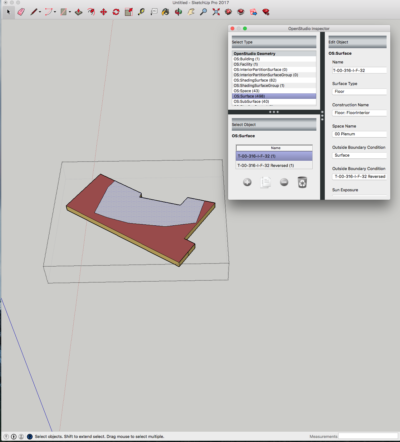
<CADObjectId>Floor: FloorInterior [13194]</CADObjectId>
<Name>T-00-316-I-F-32</Name>
</Surface>
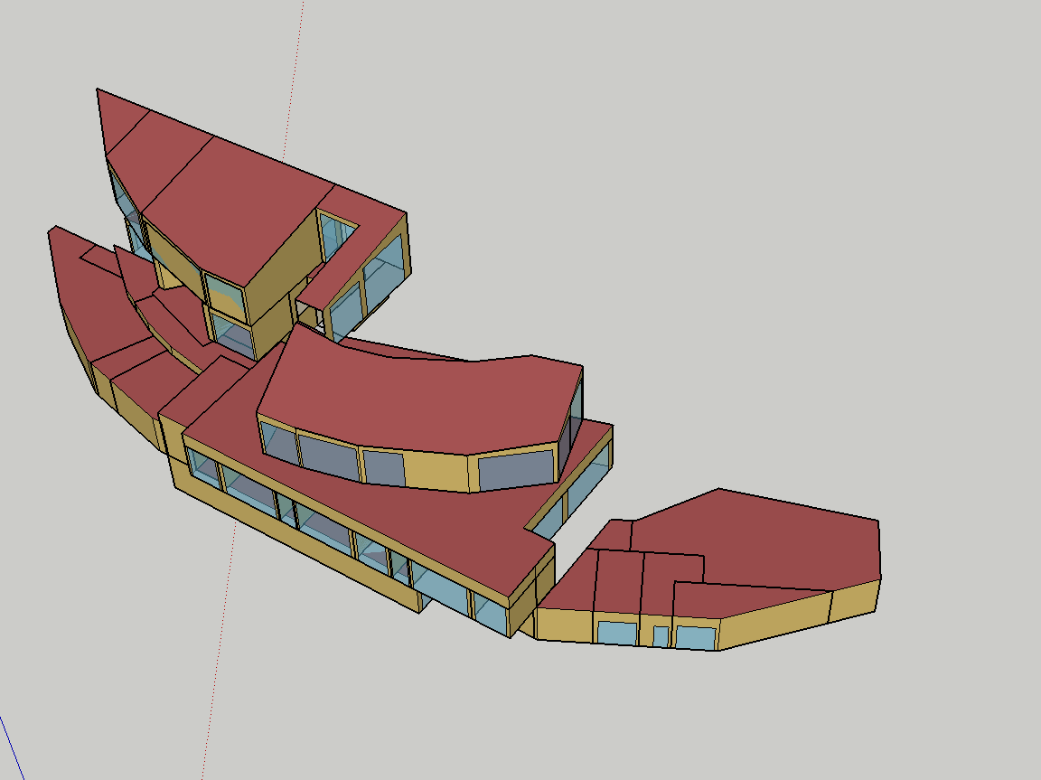
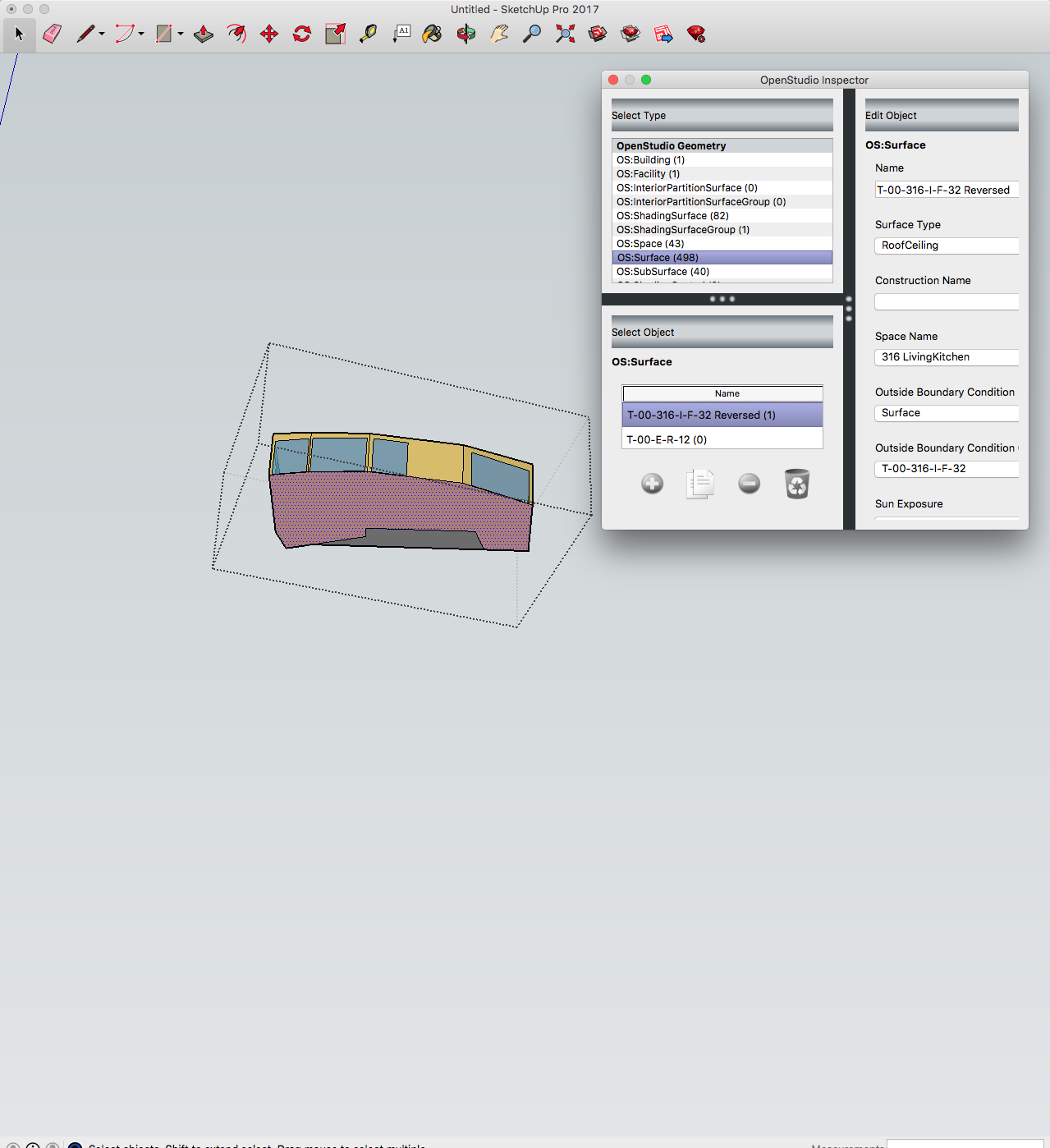
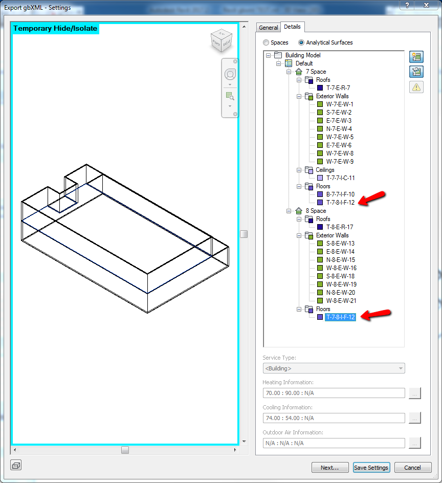
Some screenshots of one of the problem surfaces in SketchUp shown below for reference.
When you say "fix the surface normals", do you mean edit the gbxml file to swap the order of these two lines? line 1: <adjacentspaceid spaceidref="aim0154"/> line 2: <adjacentspaceid spaceidref="aim3186"/>
@Dinosaver, one thing to consider is that Revit thinks the example surface shown above is a "top" surface, as indicated by the "T" in the surface name from Revit: "T-00-316-I-F-32". If I understand the nomenclature from Revit correctly, the surface name codes something like:"surface orientation-"owning"/parent space #-adjacent space#-(int/ext) exposure-surface class (e.g. F(loor), R(oof), W(all)- incrementing unique ID". (space #s generated in order of space creation.) Sometimes Revit will show an interior floor as a "T" (top) surface and sometimes it will show as a "B" (bottom). Why is this?.
...Anyone know?...Is it vertex order? When generating a floor or roof surface from a footprint in Revit, one does not select the order of vertices. Possibly you can by selecting wall surfaces in a specific order? Please refer to my answer below for further info - it seems that order of space placement determines this.
@Molly Curtz, good points. I think many applications, including OpenStudio, can improve how they read and write gbXML for better interoperability. In this case I left the surface normal (which for OpenStudio is all about the points, not the tilt field) alone, and just changed the order of the two lines that refer to "adjacentspaceid" as you suggested in the first comment. Thanks for the information on the Revit naming logic.
This is a follow up to my above comments, which may allow you to address your issue within Revit, prior to generating the gbxml file. I just looked at a simple two space test model in Revit and found that the order that spaces are placed in Revit, will impact whether the internal floor surface is coded as "T" top of the lower space, or "B" bottom of the upper space. In the first image, space 5 is the upper space, and it was placed first. In this case, it "owns" the floor surface and it is named as the "B" (bottom) of space 5; The surface name is: "B-5-6-I-F-10"
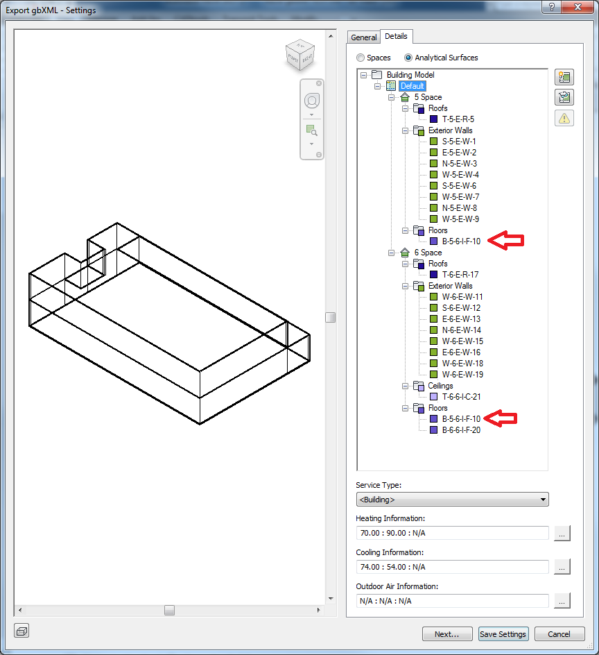
In the second image, space 8 is the upper space, and it was placed second. In this case, space 7 "owns" the floor surface (presumably since it was placed first) and the surface is named as the "T" (top) of space 7; The surface name is: "T-7-8-I-F-12"
Interesting that two models that are structurally the same, would export differently based on the order elements were drawn in. Ideally Revit could always choose one way or the other for any floor/ceiling boundaries, but really even as it is, if the vertices were also reversed with this choice it would come into OpenStudio fine. You are dealing with asymmetrical constructions (in most cases) and it is important to get them oriented correctly.
There can't be such a simple tie breaker on wall to all connections, but those are often symmetrical, but if vertices are in sync then won't matter.
@David Goldwasser: I just want to clarify that the space bounding element objects (walls, floors, roofs) were not changed or redrawn in the two cases. Rather, the space objects (which are bound by the walls, floors, roofs) were "placed" (i.e. instantiated) in the Revit model in a different order.
@Molly Curtz I've never noticed that in Revit... But technicaly speaking, things are simpler - gbXML schema is invariant to surfaces normals! It is one of its many advantages. Only adjacent spaces order matters - first layer in referenced construction contacts second adjacent space, last layer belongs to the first space. Kind of "from outside to inside", but more explicit than in E+. I will double check this. What I am afraid of is that OS relies on computed normals to determine layers order - that would be definitely wrong and prone to errors... Macumber?
@Dinosaver, If only adjacent spaces order matters, doesn't that raise the question: "how does Revit determine this order when generating the gbxml?" From the info here it looks like outward facing normal is used. Were you able to check to see if deleting those two spaces and replacing them by placing the upper space first followed by the lower space, "fixes" your issue when you import the generated gbxml into OS?
Please start posting anonymously - your entry will be published after you log in or create a new account.

Asked: 2017-05-21 04:00:58 -0500
Seen: 403 times
Last updated: Jun 30 '17


Can you provide some additional information, or link to file posted site like Google Drive or Dropbox. My first guess is that the face normal of the gbXML may either be pointing the wrong direction in Revit, or OpenStudio is interpreting it incorrectly. While gbXML has a single surface that is referenced by multiple spaces, OpenStudio and EnergyPlus have unique surfaces in each zone which then are matched to each other. OpenStudio has code to handle matched surfaces that don't either have a symmetrical construction, or mirrored construction. It seems to be applying it in this case.
Someone deleted the original gbXML so here is the link to Dropbox. BTW OS not only reverses the floor construction - it reverses the whole surface, e.g floor becomes a roof and has 0 tilt. It is very difficult to control what happens after OS imports gbXML...
@David Goldwasser, would you please explain what you mean by "matched surfaces that don't either have a symmetrical construction, or mirrored construction"? Is the original question only an issue for partially exposed roof/floor surfaces?
@Molly Curtz, in EnergyPlus when you model a wall that sits between two thermal zones, two separate surface objects are created in the IDF file each which refer to their own construction and are contained by different thermal zones. The geometry of these surfaces are identical except for the face normal being reversed. The face normal isn't set with a specific field, instead it is determined by the vertices. Since the surfaces represent mirrors of the same physical wall, the constructions assigned to them should be reverse of each other, OpenStudio validates this when possible.