Using the Indoor Air Quality option for DCV, why isn't the zone CO2 setpoint achieved?


In Energy Plus, I am using the Indoor Air Quality (Contaminant concentration modeling) approach to simulate DCV. The zone CO2 setpoint of 1100 ppm is not met.
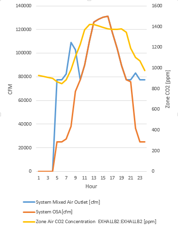
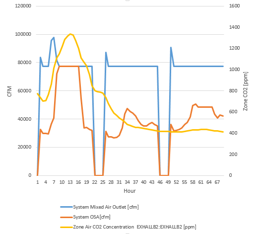
Below are graphs for one system, showing a "high" occupancy day in the first graph, and a "normal" occupancy day followed by two "low" occupancy days in the second graph; system cfm flow is plotted the left axis (blue = mixed air, orange = outside air) and zone C02 ppm (yellow) on the right axis. Looking at these it seems to me that although the zone CO2 setpoint is not met, the system airflow will not increase above what would be provided for space conditioning. On the "normal" day graph, the outside air (orange) is capped at the system minimum flow rate (sum of all connected terminal min flows). On the "high" day graph, the system flow increases above the system minimum, but this seems to be driven by space load rather than by CO2 concentration, as the zone CO2 setpoint is still not met.
"high" occupancy day:
"Normal" followed by two "low" occupancy days:
I found this post that I think is related, regarding using EMS to increase zone flow due to CO2 concentration. Is EMS the only way to do this?
As requested, here are some representative objects related to the DCV setup from my file:
DesignSpecification:OutdoorAir,
Exhall_OA,               !- Name
Sum,                     !- Outdoor Air Method
0.0031,                  !- Outdoor Air Flow per Person {m3/s-person}
0.0004;                  !- Outdoor Air Flow per Zone Floor Area {m3/s-m2}

ZoneControl:ContaminantController,
ExHallB2 DCV,            !- Name
ExHallB2:ExHallB2,       !- Zone Name
ALL ON,                  !- Carbon Dioxide Control Availability Schedule Name
Indoor CO2 Setpoint;     !- Carbon Dioxide Setpoint Schedule Name

Schedule:Constant,
Indoor CO2 Setpoint,     !- Name
Any Number,              !- Schedule Type Limits Name
1100;                    !- Hourly Value

Sizing:Zone,
ExHallB2:ExHallB2,       !- Zone or ZoneList Name
SupplyAirTemperature,    !- Zone Cooling Design Supply Air Temperature Input Method
15.3,                    !- Zone Cooling Design Supply Air Temperature {C}
,                        !- Zone Cooling Design Supply Air Temperature Difference {deltaC}
TemperatureDifference,   !- Zone Heating Design Supply Air Temperature Input Method
,                        !- Zone Heating Design Supply Air Temperature {C}
11,                      !- Zone Heating Design Supply Air Temperature Difference {deltaC}
0.0084,                  !- Zone Cooling Design Supply Air Humidity Ratio {kgWater/kgDryAir}
0.0026,                  !- Zone Heating Design Supply Air Humidity Ratio {kgWater/kgDryAir}
ExHall_OA,               !- Design Specification Outdoor Air Object Name
,                        !- Zone Heating Sizing Factor
,                        !- Zone Cooling Sizing Factor
DesignDay,               !- Cooling Design Air Flow Method
,                        !- Cooling Design Air Flow Rate {m3/s}
,                        !- Cooling Minimum Air Flow per Zone Floor Area {m3/s-m2}
,                        !- Cooling Minimum Air Flow {m3/s}
,                        !- Cooling Minimum Air Flow Fraction
DesignDay,               !- Heating Design Air Flow Method
,                        !- Heating Design Air Flow Rate {m3/s}
,                        !- Heating Maximum Air Flow per Zone Floor Area {m3/s-m2}
,                        !- Heating Maximum Air Flow {m3/s}
,                        !- Heating Maximum Air Flow Fraction
DSZAD;                   !- Design Specification Zone Air Distribution Object Name

Controller:OutdoorAir,
BF VAV System OA Controller,  !- Name
BF VAV System Relief Air Outlet,  !- Relief Air Outlet Node Name
BF VAV System Return Fan Outlet,  !- Return Air Node Name
BF VAV System Mixed Air Outlet,  !- Mixed Air ...

Did you include the
ZoneControl:ContaminantControllers? Can you post yourController:MechanicalVentilationand some of yourZoneControl:ContaminantController?Yes. I will edit my question to provide examples of the requested objects.Let me know if I left out any relevant ones. Sorry - I can't seem to get the Sizing:Zone object to format as a code block for some reason.
(a code block must start with at 4 spaces, you were just missing them for Sizing:Zone)
How is your AirLoopHVAC controlled?
SetpointManager:Scheduled?@Julien Marrec, thanks for improving the formatting on my question! A setpoint at the supply fan outlet node is set by a
SetpointManager:Warmest(11.1C to 29.4C), and a setpoint at the supply path inlet node is set by aSetpointManager:Scheduledso that the heating coil will operate to provide a minimum supply air temp (10C).