Question-and-Answer Resource for the Building Energy Modeling Community
Get started with the Help page
Ask Your Question
4

Why don't my parallel water heaters both supply heat?

asked 2015-01-07 07:25:56 -0500

updated 2015-01-09 12:01:55 -0500

I have two WaterHeater:Mixed objects in parallel, one with a setpoint of 50 C (Water Heater) and one with a setpoint of 80 C 75 C (PCM tank). This is the order they are listed in the EquipmentList so the one with a lower setpoint is drawn on first.

image description

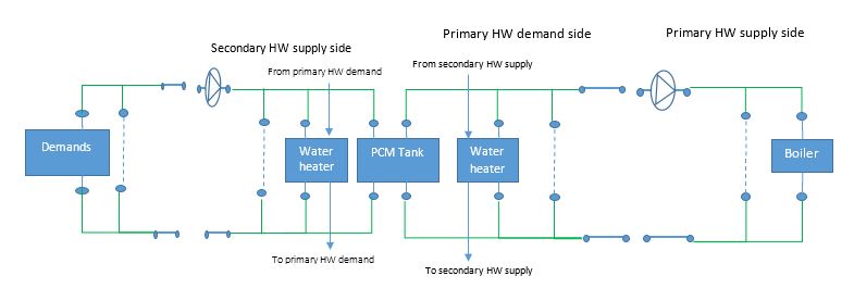
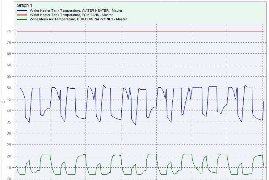
The question is why is the second tank not drawn from when the first tank can't meet the load?

image description

Edited to add section of IDF

PlantLoop,
   Secondary HW Loop,                               ! - Name of loop
   Water,                                  ! - Fluid type
   ,                                       ! - User-defined fluid type
   Secondary HW Loop Operation,                                    ! - Plant equipment operation scheme
   Secondary HW Loop Supply Side Outlet,                           ! - Loop temperature setpoint node
   80.00,                                  ! - Maximum loop temperature (C)
   0.00,                                   ! - Minimum loop temperature (C)
   autosize,                               ! - Maximum loop flow rate (m3/s)
   0.000000,                               ! - Minimum loop flow rate (m3/s)
   autocalculate,                          ! - Volume of the plant loop (m3)
   Secondary HW Loop Supply Side Inlet,                            ! - Plant side inlet node
   Secondary HW Loop Supply Side Outlet,                           ! - Plant side outlet node
   Secondary HW Loop Supply Side Branches,                         ! - Plant side branch list name
   Secondary HW Loop Supply Side Connectors,                       ! - Plant side connector list name
   Secondary HW Loop Demand Side Inlet,                            ! - Demand side inlet node
   Secondary HW Loop Demand Side Outlet,                           ! - Demand side outlet node
   Secondary HW Loop Demand Side Branches,                         ! - Demand side branch list name
   Secondary HW Loop Demand Side Connectors,                       ! - Demand side connector list name
   Uniform,                             ! - Load distribution scheme
   Secondary HW Loop AvailabilityManager List,                     ! - Availability manager list name
   SingleSetpoint,                         ! - Plant loop demand calculation scheme
   None,                                   ! - Common pipe simulation
   None;                                   ! - Pressure simulation type

PlantEquipmentOperationSchemes,
   Secondary HW Loop Operation,                                    ! - Name of plant/condenser equipment operation scheme
   PlantEquipmentOperation:HeatingLoad,                   ! - Control scheme object type 1
   Secondary HW Loop Scheme 1,                      ! - Name of control scheme 1
   On;                                      ! - Control scheme schedule 1

PlantEquipmentOperation:HeatingLoad,
   Secondary HW Loop Scheme 1,                      ! - Name of control scheme
   0.00,                                   ! - Range lower limit 1
   1000000000000000.00,                                   ! - Range upper limit 1
   Secondary HW Loop  Scheme 1 Range 1 Equipment List;             ! - Range equipment list name 1

PlantEquipmentList,
   Secondary HW Loop  Scheme 1 Range 1 Equipment List,             ! - Range equipment list name 0
   WaterHeater:Mixed,                      ! - Equipment 1 object type
   Water Heater,                           ! - Equipment 1 name
   WaterHeater:Mixed,                      ! - Equipment 1 object type
   PCM Tank;                           ! - Equipment 1 name
edit retag flag offensive close merge delete

Comments

I don't see any obvious reasons right off the bat and I haven't tried this before. Any chance you could share the idf, or the relevant sections for those parallel branches? Are you seeing any flow through the 80°C branch?

Julien Marrec's avatar Julien Marrec  ( 2015-01-07 07:46:47 -0500 )edit

Apparently we can't upload IDFs here. The relevant section is in this pastebin.

Jamie Bull's avatar Jamie Bull  ( 2015-01-07 08:06:26 -0500 )edit

And no, no flow at all through the 80°C branch.

Jamie Bull's avatar Jamie Bull  ( 2015-01-07 08:17:14 -0500 )edit

2 Answers

Sort by » oldest newest most voted
6

answered 2015-01-07 10:47:46 -0500

updated 2015-01-07 10:56:06 -0500

Thanks to the BigLadder EnergyPlus support service this is now working as expected. I needed to switch out the PlantEquipmentOperation:HeatingLoad object for a PlantEquipmentOperation:ComponentSetpoint object then add SetpointManagers for each tank outlet.

Here's the section from the question with the changes needed.

PlantLoop,
   Secondary HW Loop,                                    ! - Name of loop
   Water,                                       ! - Fluid type
   ,                                            ! - User-defined fluid type
   Secondary HW Loop Operation,                          ! - Plant equipment operation scheme
   Secondary HW Loop Supply Side Outlet,                 ! - Loop temperature setpoint node
   80.00,                                       ! - Maximum loop temperature (C)
   0.00,                                        ! - Minimum loop temperature (C)
   autosize,                                    ! - Maximum loop flow rate (m3/s)
   0.000000,                                    ! - Minimum loop flow rate (m3/s)
   autocalculate,                               ! - Volume of the plant loop (m3)
   Secondary HW Loop Supply Side Inlet,                  ! - Plant side inlet node
   Secondary HW Loop Supply Side Outlet,                 ! - Plant side outlet node
   Secondary HW Loop Supply Side Branches,               ! - Plant side branch list name
   Secondary HW Loop Supply Side Connectors,             ! - Plant side connector list name
   Secondary HW Loop Demand Side Inlet,                  ! - Demand side inlet node
   Secondary HW Loop Demand Side Outlet,                 ! - Demand side outlet node
   Secondary HW Loop Demand Side Branches,               ! - Demand side branch list name
   Secondary HW Loop Demand Side Connectors,             ! - Demand side connector list name
   Sequential,                                  ! - Load distribution scheme
   Secondary HW Loop AvailabilityManager List,           ! - Availability manager list name
   SingleSetpoint,                              ! - Plant loop demand calculation scheme
   None,                                        ! - Common pipe simulation
   None;                                        ! - Pressure simulation type

PlantEquipmentOperationSchemes,
   Secondary HW Loop Operation,                          ! - Name of plant/condenser equipment operation scheme
   PlantEquipmentOperation:ComponentSetpoint,         ! - Control scheme object type 1
   Secondary HW Loop Scheme 1,                           ! - Name of control scheme 1
   On;                                           ! - Control scheme schedule 1

SetpointManager:Scheduled,
   PCM_Setpoint_Manager,  !- Name
   Temperature,                !- Control Variable
   PCM Tank Temp Schedule,  !- Schedule Name
   PCM Tank Primary Outlet Node;      !- Setpoint Node or NodeList Name

SetpointManager:Scheduled,
   WaterHeater_Setpoint_Manager,  !- Name
   Temperature,                !- Control Variable
   Main Water Heater Tank Temp Schedule,  !- Schedule Name
   Water Heater Primary Outlet Node;      !- Setpoint Node or NodeList Name

PlantEquipmentOperation:ComponentSetpoint,
    Secondary HW Loop Scheme 1,
    WaterHeater:Mixed,        !- Equipment 1 Object Type
    Water Heater,          !- Equipment 1 Name
    Water Heater Primary Inlet Node, !- Demand Calculation 1 Node Name
    Water Heater Primary Outlet Node, !- Setpoint 1 Node Name
    autosize,                     !- Component 1 Flow Rate
    Heating,                    !- Operation 1 Type
    WaterHeater:Mixed,        !- Equipment 2 Object Type
    PCM Tank,             !- Equipment 2 Name
    PCM Tank Primary Inlet Node,  !- Demand Calculation 2 Node Name
    PCM Tank Primary Outlet Node, !- Setpoint 2 Node Name
    autosize,                  !- Component 2 Flow Rate
    Heating;                 !- Operation 2 Type
edit flag offensive delete link more
2

answered 2015-01-07 09:38:46 -0500

Try setting the "Load Distribution Scheme" in the PlantLoop object to "Uniform" not "Sequential". You may also need to alter the associated "PlantEquipmentOperation:HeatingLoad" object.

edit flag offensive delete link more

Comments

Just changing Sequential to Uniform gives the same results. What do I need to change in the PlantEquipmentOperation:HeatingLoad? I've added the relevant objects to the question.

Jamie Bull's avatar Jamie Bull  ( 2015-01-07 09:55:34 -0500 )edit

This may not be the only problem but you need to define upper and lower limits for both pieces of equipment that serve that loop. You have only defined limits for one. Take a look at the InputOutputReference.pdf for more details.

Lincoln's avatar Lincoln  ( 2015-01-07 10:14:51 -0500 )edit

I think he did already, unless I'm reading it incorrectly. The PlantEquipmentOperation:HeatingLoad applies to the equipment list which has both tanks in it. No?

Julien Marrec's avatar Julien Marrec  ( 2015-01-07 10:38:12 -0500 )edit

That's right, it applies to both. The guys on the BigLadder support service have just come back with the right answer though. I needed to switch out the PlantEquipmentOperation:HeatingLoad object for a PlantEquipmentOperation:ComponentSetpoint object then add SetpointManagers for each tank outlet.

Jamie Bull's avatar Jamie Bull  ( 2015-01-07 10:42:54 -0500 )edit

Your Answer

Please start posting anonymously - your entry will be published after you log in or create a new account.

Add Answer

Careers

Question Tools

1 follower

Stats

Asked: 2015-01-07 07:25:56 -0500

Seen: 287 times

Last updated: Jan 07 '15