Question-and-Answer Resource for the Building Energy Modeling Community
Get started with the Help page
Ask Your Question
5

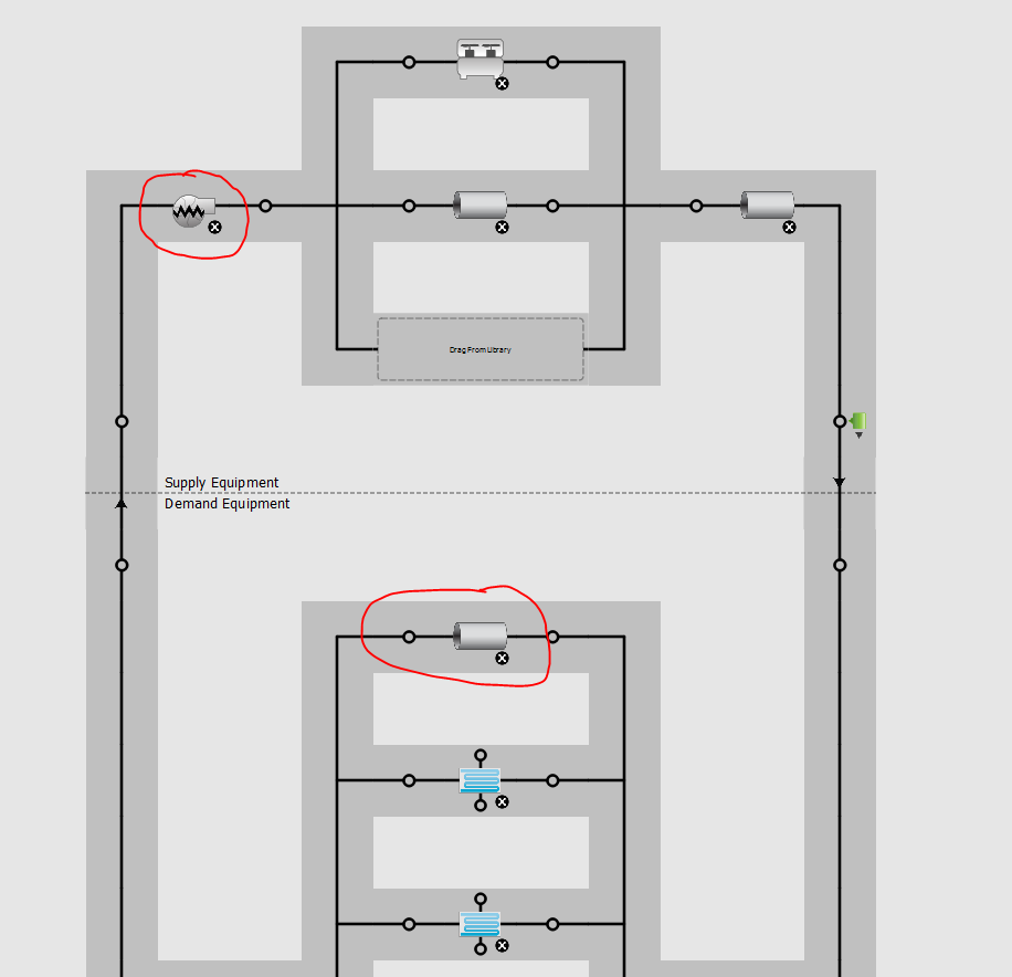
three-way valve or bypass valve in chilled water loop

asked 2016-06-01 10:12:10 -0500

Matt Koch's avatar

updated 2016-06-03 05:23:48 -0500

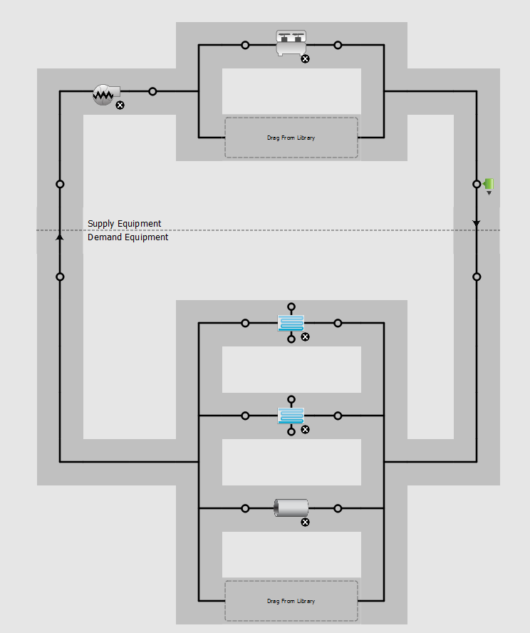
In assembling a fairly detailed OpenStudio/EnergyPlus model of a building, I realized I may need to more accurately model the chilled water loop. At present, my loop only has a chiller, a variable speed pump and two air handlers (in parallel), whereby it appears as though the inlet nodes to the air handlers act as "two-way" valves (?).

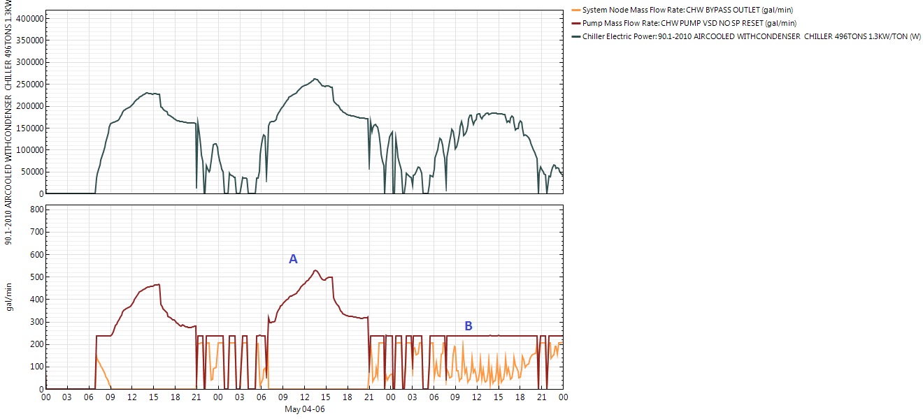
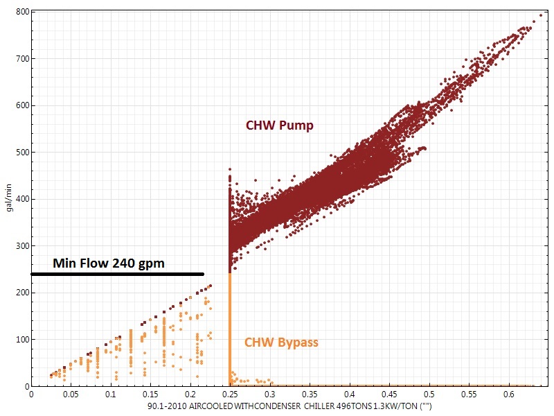
In actuality, one of the air handlers has a three-way valve with a bypass straight from the chilled water supply to the return line, i.e. when this air handler does not need all the cooling it can get, it simply bypasses the chilled water and contributes to a "low delta T" condition. Even if this three-way valve was not there, there would still have to be a bypass valve in this variable primary loop so as to ensure the chiller always sees its minimum flow requirement met (of course, this also contributes to a "low delta T" condition - necessarily so).

So, my question is, can these types of valves (and associated pipe runs) be accommodated by OpenStudio/EnergyPlus in order to more realistically represent the chilled water loop? I would imagine this configuration would make the pump work harder and/or make the chiller operate less efficiently and therefore would have a non-negligible impact on energy consumption?

edit retag flag offensive close merge delete

3 Answers

Sort by ยป oldest newest most voted
2

answered 2016-06-02 18:19:55 -0500

updated 2016-06-02 22:53:21 -0500

I believe the system that you're describing is supported by EnergyPlus/OpenStudio. However, there is not an explicit "3-way valve" option in EnergyPlys like there is in eQUEST. Personally, I think this is a good thing because it requires the modeler to think more about how the system is operating.

As a crude first guess you could set the minimum flow rates on the secondary pump and loop to be equivalent to the rated flow rate of the three-way valve(s). If this is an existing building, trend data will be necessary to figure out what that minimum flow setting should really be. In reality it's probably higher than the rated flow rate of the three-way valve(s).

Checkout this post for more information on modeling primary/secondary loops in OpenStudio/EnergyPlus

edit flag offensive delete link more

Comments

Thank you Lincoln. The primary/secondary loop link you sent has some interesting insight, even though I do not understand why the EnergyPlus team discourages the common pipe and encourages instead the fluid-to-fluid heat exchanger. It seems to me that these two are not really equivalent at all, at least not hydraulically, and at least on the surface not thermally. Would one use an "ideal" heat exchanger here?

Matt Koch's avatar Matt Koch  ( 2016-06-03 07:16:33 -0500 )edit

Regarding my loop, it is a variable primary loop only, with a three-way valve rather than a two-way bypass valve. If OpenStudio can handle a primary/secondary loop, surely it must be able to handle a variable primary loop. So perhaps it is time for me to dig deeper into the plant guide. My concern with what you suggest is that I might capture the minimum flow OK, but how will I account for normal operation, where flow may be split in all kinds of different ways among air handler 1, air handler 2 and that three-way valve leg that effectively shorts supply to return?

Matt Koch's avatar Matt Koch  ( 2016-06-03 07:21:41 -0500 )edit
5

answered 2016-06-04 15:52:55 -0500

updated 2016-06-05 15:23:43 -0500

I just did a quick test and I believe this configuration is what you're looking for:

  1. Set up the CHW loop as shown in the picture below
    • Put a bypass Pipe:Adiabatic on the demand side.
    • Put aPump:VariableSpeed on the supply side.
  2. In the Chiller:Electric:EIR
    • Set the 'Chiller Flow Mode' to 'NotModulated'
  3. In the PlantLoop
    • Set the 'Minimum Loop Flow' rate to your minimum. For my test I arbitrarily picked 240 gpm, which was 20% of the loop design flow rate.
  4. In the Pump:VariableSpeed
    • Set the 'Minimum Flow Rate' rate to your minimum
    • Set the 'Pump Control Type' to intermittent (the pump shuts off when there is no demand on the loop)

image description

Here's the result (sorry the pictures are so small):

At Point A, the Chiller (black, top) is running and the pump (red, bottom) is pumping above the minimum flow rate but there's no flow through the bypass (orange, bottom).

At Point B, the Chiller (black, top) is running at a lower power. The pump (red, bottom) is pumping at the minimum flow rate even though the coils aren't calling for flow. Whatever the coils don't need flows through the bypass (orange, bottom).

image description

In this plot of CHW pump and CHW bypass vs. Chiller part load, you can see that when the chilled water pump (red) is above the minimum flow (horizontal black line), there is barely ever any flow through the bypass (orange). However, when the chilled water pump is at minimum flow, there is often lots of flow through the bypass, with the bypass flow topping out at the minimum CHW flow rate.

image description

edit flag offensive delete link more

Comments

(for picture size put the picture in a link. [![image descp](link)](link) that way you can click it to enlarge

Julien Marrec's avatar Julien Marrec  ( 2016-06-05 15:25:12 -0500 )edit

Wow, thank you SO much! This is a great example of providing practical and actionable support! Way beyond the call of duty, too. Overall, do I understand correctly that EnergyPlus always calculates what water flows the coils need and then makes the pumps run that way, unless there is a minimum flow associated with the pump (or loop)? If there were no bypass lines, how would EnergyPlus establish that minimum flow? Would it allow flow through the coils, even though they may not need as much?

Matt Koch's avatar Matt Koch  ( 2016-06-06 06:58:01 -0500 )edit

Furthermore, if there was a bypass line on the demand (but not supply) side, would that not suffice? With a bypass line on the supply side, it seems to me it is not clear what the split between chiller and its bypass line should be? I think as I get back into this hopefully later today, I will try that, too.

Matt Koch's avatar Matt Koch  ( 2016-06-06 07:00:37 -0500 )edit

Finally, the there graphs you provided are enormously helpful in figuring out what goes on in the system. were these something you could select in OpenStudio, or did you have hand-edit some IDF file?

Matt Koch's avatar Matt Koch  ( 2016-06-06 07:01:43 -0500 )edit

Based on my observations, yes, I think your understanding of how E+ determines flow is correct. The Engineering Reference also has some pretty good documentation about how the pumps are controlled.

aparker's avatar aparker  ( 2016-06-07 16:47:08 -0500 )edit
1

answered 2016-06-06 11:43:51 -0500

Matt Koch's avatar

So, it seems that with this plant loop:

image description,

I get this pump flow:

image description.

The low range is about 6.31 kg/s, corresponding to 100 gpm. The high range falls somewhat short of the 13.56 kg/s or 215 gpm that the loop was designed to go to, but I suppose that is so because full flow is not really needed to meet the load. Interestingly, setting the plant loop to 100 gpm minimum was not sufficient, I also had to set the pump to 100 gpm minimum, rather than the 77.2 gpm that is actually could go to. Also, I left the pump at "continuous" rather than "intermittent", as it should have to run even when there are no loads on the coils. I think this is close to what I needed, so thanks again for setting me on the right track! HOWEVER, I do not know how to plot the flow through the bypass or the AHU (there seem to be no variables for that in the .rdd file), so any help with that would still be much appreciated.

edit flag offensive delete link more

Comments

You can get the flow through the bypass by using the 'System Node Standard Density Volume Flow Rate' output variable, and specifying the name of the node immediately up- or down-stream of the bypass pipe as the key value.

ericringold's avatar ericringold  ( 2016-06-06 11:49:35 -0500 )edit

OK, I could not find "System Node Standard Density Volume Flow Rate", but I did find the Node Diagnostics measure and applied it to the nodes I am interested in. In combination with readvarseso.exe and a suitable .rvi file, I can get these into Excel, and confirm that the minimum flow for the chiller is indeed met, and that the bypass indeed sees nothing as long as the coils demand more than the minimum flow. I think this is close enough for my purposes. Again, thank you all for helping me out. You have provided very, very useful advice.

Matt Koch's avatar Matt Koch  ( 2016-06-08 07:49:16 -0500 )edit

Very interesting. This does not work at all when replacing the Variable Speed Pump with a Headered Variable Speed Pump. Also, the above image by aparker of chiller electrical power, pump flow rate and bypass flow rate as a function of time shows the pump flow rate dropping to zero when there is no cooling demand. This behavior changes when the variable speed pump is moved from outside to inside the chiller branch, and when there are two parallel variable speed pump/chiller pairs instead of one. Then, the pump flow rate never drops below the minimum. A never-ending parade of wonders.

Matt Koch's avatar Matt Koch  ( 2017-10-26 18:04:09 -0500 )edit

Hi Matt - my experience is that with multiple chillers each with a branch pump, the approach shown by Julien will not work as desired. I (reluctantly) implemented a EMS approach to get it to work. A simpler approach to the EMS method, which I have not implemented (because it is loathsome to me) would be to schedule the required bypass flow (use a PlantLoad:Profile).

TomB's avatar TomB  ( 2019-05-18 16:03:30 -0500 )edit

Your Answer

Please start posting anonymously - your entry will be published after you log in or create a new account.

Add Answer

Careers

Question Tools

2 followers

Stats

Asked: 2016-06-01 10:12:10 -0500

Seen: 7,707 times

Last updated: Jun 06 '16