Question-and-Answer Resource for the Building Energy Modeling Community
Get started with the Help page
Ask Your Question
1

Unable to find error resoltion

asked 2016-02-23 14:10:07 -0500

shopengarten's avatar

Hey All,

New openstudio user here, and I'm trying to make my first simulation, however I keep getting the same error.

On more then one occasion I keep getting this same error for all of my heating coils:

* Severe * IP: IDF line~912 Error detected in Object=COIL:HEATING:WATER, name=UNIT HEATER HW HTG COIL 10 * ~~~ * Field [Water Inlet Node Name] is required but was blank *** IDF Context for following error/warning message: *** Note -- lines truncated at 300 characters, if necessary... *** 907 Coil:Heating:Water, *** indicated Name=Unit Heater HW Htg Coil 10 *** Only last 6 lines before error line shown..... *** 908 Unit Heater HW Htg Coil 10, !- Name *** 909 Always On Discrete 1, !- Availability Schedule Name *** 910 Autosize, !- U-Factor Times Area Value {W/K} *** 911 Autosize, !- Maximum Water Flow Rate {m3/s} *** 912 , !- Water Inlet Node Name *** 913 , !- Water Outlet Node Name

How can I map the node names correctly so I can run my model?

Thanks.

edit retag flag offensive close merge delete

Comments

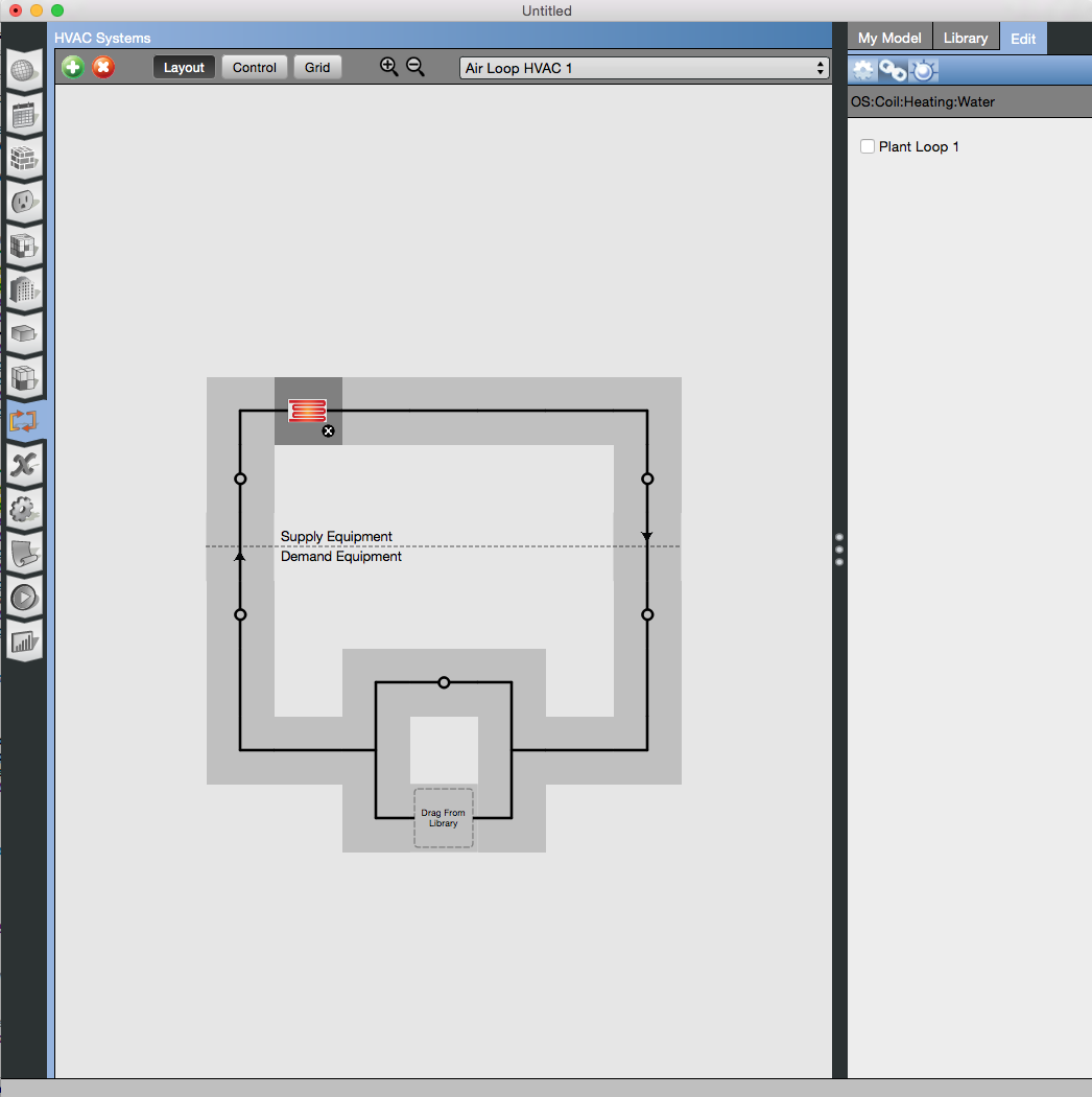
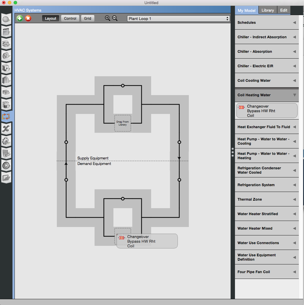
How did you make your HVAC system? Looks like you may have a water coil that isn't connected to a plant loop. If not on an air loop, check terminals and zone equipment.

Field [Water Inlet Node Name] is required but was blank
David Goldwasser's avatar David Goldwasser  ( 2016-02-24 10:48:38 -0500 )edit

I couldn't figure out how to tie my air loop or water loop to my existing chilled water loop or hot water loop and I can't find any tutorials. I was assuming that OpenStudio automatically connected the unit to my existing hot water loop.

Thanks!

shopengarten's avatar shopengarten  ( 2016-02-24 11:05:43 -0500 )edit

1 Answer

Sort by ยป oldest newest most voted
1

answered 2016-02-24 12:14:25 -0500

There are two options. You can select the coil in your air loop and then choose the sub-tab in the edit window that looks like a chain. This allows you to select the plant loop to connect it with. If you scroll down from this link on Air Loop documentation you will see a screenshot that shows an air loop with the cooling coil selected. In the edit tab the three sub-tabs are labeled. The one that looks like a chain is where you can connect the coil to a loop. Here is a screenshot of the first approach.

image description

An alternative approach after adding a coil to the supply side of an air loop, is to go the plant loop you want to link it to, and then drag it from "My Model" to the demand side of the plant loop. It will then have the dot above and below it that lets you jump between the loops it is on. Here is a screenshot of the second approach.

image description

With either solution you coil should end up looking like this. image description

edit flag offensive delete link more

Your Answer

Please start posting anonymously - your entry will be published after you log in or create a new account.

Add Answer

Careers

Question Tools

1 follower

Stats

Asked: 2016-02-23 14:10:07 -0500

Seen: 306 times

Last updated: Feb 24 '16