Question-and-Answer Resource for the Building Energy Modeling Community
Get started with the Help page
Ask Your Question
4

AHU and ERV Contruction [closed]

asked 2016-02-18 07:41:09 -0500

Dustin's avatar

updated 2017-05-17 12:53:55 -0500

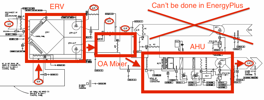
I am wondering if I went about modelling this AHU and ERV system correctly. Below is the schematic for the system.

image description

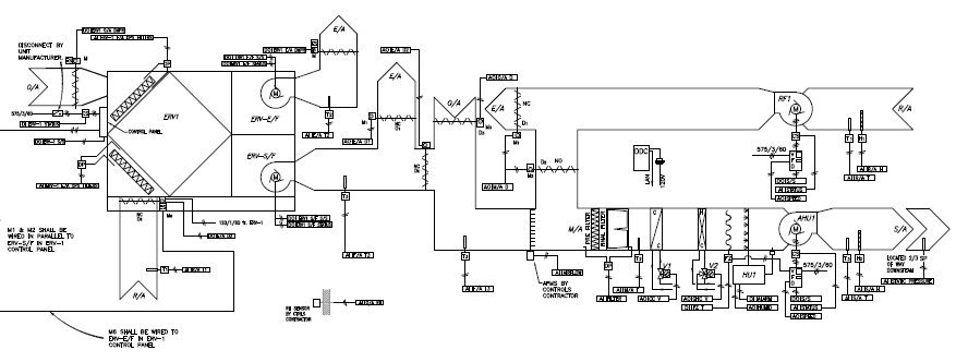
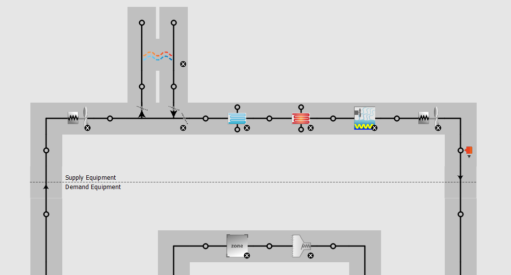
When I modelled it I created my AHU (the right side of the image) using an air loop and the appropriate components. I then simply put an ERV HX on the supply and exhaust nodes of the outdoor air controller. Going back and looking at the schematic I am now thinking I might have over simplified things and that is why some of my results are not as expected.

If anyone can give me any insight on how I could model this or if I did initially model it correctly. Should be noted I do my initial work in OpenStudio and do the fine tuning in E+.

edit retag flag offensive reopen merge delete

Closed for the following reason the question is answered, right answer was accepted by Dustin
close date 2017-01-13 06:53:58.276692

3 Answers

Sort by ยป oldest newest most voted
6

answered 2016-02-18 11:59:11 -0500

You're correct, placing the ERV HX on the supply and exhaust nodes of the outdoor air mixer DOES NOT MATCH the schematic above. To match, the ERV HX should be placed between the return air node and the outdoor air mixer. Reference my annotated image of your schematic, where red boxes represent HVAC components, circles are for important air nodes, and arrows show flow of process air.

image description

There are two big issues I see with modeling this exact system:

  • EnergyPlus has a AirLoopHVAC:OutdoorAirSystem object that serves as the sub-system that introduces outdoor air and has a list of equipment that shape the outdoor air system. According to the Engineering Reference for this object:

    The OutdoorAir:Mixer should be the first component in the AirLoopHVAC:OutdoorAirSystem:EquipmentList object.
    

You can try to connect the ERV as a stand-alone component that isn't part of the outdoor air system. Again, the inlet for the ERV process air should be return air and the outlet for the ERV process air should be the same as the inlet for the OA mixer process air.

  • I'm ~90% sure that EnergyPlus won't allow the second return air path and exhaust outlet in parallel that bypasses the ERV/ OA mixer and enters the AHU. You'll need to test this out by placing a AirLoopHVAC:ZoneSplitter object before the ERV, and a AirLoopHVAC:ZoneMixer object after the OA mixer. Documentation for both of these objects states they must be on the demand loop (supply path or return path) of air systems, NOT the supply loop. You'll also need to make sure the AirLoopHVAC object references the multiple Branches and Connectors accordingly. Like @Eric Ringold stated above, the "Heat Recovery Bypass Control Type" input field of the OA controller object may be the closest you can get.

Good Luck!

edit flag offensive delete link more

Comments

Good call on the system breakdown, @Aaron Boranian, I missed the second return air path part. Note that apparently, the HeatExchanger:AirToAir:SensibleAndLatent object is now valid as a main branch component. Until they update the documentation I'm not sure how that's supposed to work, or if it will affect the 'OutdoorAirMixer first' requirement. In any case the HX is still limited to placement on the OutdoorAirSystem in OpenStudio.

ericringold's avatar ericringold  ( 2016-02-18 12:10:44 -0500 )edit
2

answered 2016-02-19 07:43:34 -0500

Dustin's avatar

Thanks for the inputs Eric and Aaron. I appreciate it and will look into the options you both provided me more. As of right now this is what I have modelled for the system and I will continue trying to refine the model to have it more accurately represent the building. image description

If you see anything that looks extremely wrong let me know. Not sure how this will affect things but the variable speed fan on the left has a higher maximum air flow rate than the Controller:OutdoorAir. It ran fine without an errors earlier and now I will just have to output some variables and verify the operation and flow rates.

Thanks again guys.

edit flag offensive delete link more
4

answered 2016-02-18 11:28:56 -0500

It looks like your AHU just has ductwork to bypass the HX. Depending on the system control sequence, the Controller:OutdoorAir input field Heat Recovery Bypass Control Type would be a way to capture this effect. Also see the HX inputs Supply Outlet Temperature Control, Economizer Lockout, and the frost control inputs.

edit flag offensive delete link more

Careers

Question Tools

1 follower

Stats

Asked: 2016-02-18 07:41:09 -0500

Seen: 1,984 times

Last updated: Jan 27 '17