Question-and-Answer Resource for the Building Energy Modeling Community
Get started with the Help page
Ask Your Question
3

Coil sizing check in E+

asked 2016-01-25 10:50:33 -0500

ngkhanh's avatar

updated 2017-05-08 15:45:46 -0500

Hello, i would like to manually verify DX coil sizing in zonal equipment. The zone coil load should include ventilation and infiltration latent load. But unfortunately E+ standard report doesn't have them in desired format (g/kg instead of W). Update from Mr. Rraustad suggestion and E+ documentation : input as follow : image description Bases on psychrometric coil sizing formula :

set  standard air density (1,2 kg/ m3)

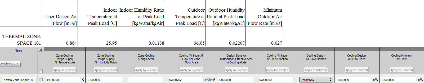
mixed air flow = User Calc air flow =0.884 m3/s = 0.857(return air flow) +0.027 (outdoor air flow)

Enthalpy outdoor (36oC, 0.02207g/kg) = 92.87 kJ/kg ;Enthalpy return air/room air (26oC, 0.01138 g/kg) = 55.21 kJ/kg

 Enthalpy supply air (14oC, 0.009 g/kg) = 36.87 kJ/kg

 Enthalpy mix = ( Outdoor air enthalpy * Outdoor air flow + Return air flow * Return outdoor enthalpy)/mixed air flow = 56.37 kJ/kg -> air temperature = 26.3 oC air density = 1.157 kg/m3 

   Performance CAPFT : x = mixed air wetbulb = 19.68 oC , y = outdoor drybulb = 36 oC

CapFT= 1.5509 + (-0.07505) * 19.68 + 0.0031 * 19.68^2 + 0.0024 * 36 + (0.00005) * 36^2 + 36 * 19.68 *(-0.00043) = 1.121

Coil capacity =  (Enthalpy mix - Enthalpy sizing zone ) * (air density) *  (airflow) /  (CapFT) 
                    =     (55.21 - 36.87) * 1.157 * 0.884 /1.121 = 17782 W

The coil report for PTAC :image description

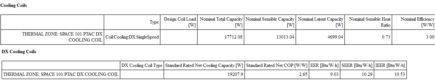
Great Thanks to Mr Rraustad for validation.

edit retag flag offensive close merge delete

Comments

Which E+ reports are you looking at?

rraustad's avatar rraustad  ( 2016-01-25 12:21:51 -0500 )edit

i look at component sizing summary and equipment summary reports. i focus on basic sizing calculations of local system like PTHP, PTAC, VAV box,...

ngkhanh's avatar ngkhanh  ( 2016-01-25 13:41:07 -0500 )edit

I stepped through the PTHP example file last night and found a match to the DX cooling coil size. I'll have to repeat that tonight. Or if you send me your file, I'll validate your coil.

rraustad's avatar rraustad  ( 2016-02-02 08:38:07 -0500 )edit

Please check here IDF link i made thermal zone 101 sizing different with other .

ngkhanh's avatar ngkhanh  ( 2016-02-02 10:51:02 -0500 )edit
1

Your file: Mixed T = 26.27, w = 0.01171, WB = 19.71, H = 56.248, rho = 1.1566, flow = 0.8838 CapFT = 1.12193, SupplyH = 36.81, Q = (56248-36810) * 1.1566 * 0.8838 / 1.12193 = 17710.2 W compared to 17712.08 W (rounding)

rraustad's avatar rraustad  ( 2016-02-02 12:38:45 -0500 )edit

1 Answer

Sort by ยป oldest newest most voted
4

answered 2016-01-25 14:31:54 -0500

updated 2016-01-26 20:16:23 -0500

The Component Sizing Summary and Equipment Summary in the table reports show the DX coil size as total capacity (sensible + latent) reported as W (or Btu/hr if requested). The zone load is reported as sensible energy to meet the zone thermostat set point temperature. Ventilation and Infiltration are included in the coil sizing if these OA components are included in the model. The coil airflow is sized to meet the zone sensible load, and then includes the DX coil capacity as a function of temperature performance curve to calculate the coil's design total capacity.

$$ Q_{coil} = \frac {\rho V ({h_{in} - h_{out})}}{CapFT}$$

where:
$Q_{coil}$ = coil total cooling capacity (sensible + latent)
$\rho$ = coil inlet air density
V = zone air volume flow rate determined by sizing routine (see *zsz.csv)
$h_{in}$ = coil inlet air enthalpy at peak time including OA
$h_{out}$ = coil outlet air enthalpy as specified in Sizing:Zone object
CapFT = capacity as a function of temperature curve output at coil inlet air temperatures

Update based on comment: The HVAC Sizing Summary report will show the values for User Design Air Flow. The indoor temperature and humidity ratio shown here does not include outdoor air. If OA is used, calculate a mixed air inlet condition using the OA fraction (OA flow/user design flow). Then use the mixed air condition to calculate coil inlet air density and enthalpy. The CapFT value is determined by entering the Indoor/Outdoor Temperature, converted to wet-bulb temperature, at Peak Load into the performance curve to find the value used in the coil sizing model.

The OA included in the coil sizing equation is the OA mixed with return air at the outdoor air system mixing box. This mixing of OA impacts the coil inlet air conditions. Infiltration will show up in the zone indoor conditions reported in HVAC Sizing Summary.

edit flag offensive delete link more

Comments

Thank a lot for formula. But it's hard to determine all those input with standard report of E+ for zonal equip like PTAC. i got from HVAC sizing summary Cooling Sensible - User Design Load (W) - it's same as zone component load summary report for sensible peak load. But how to get coil total cooling capacity (sensible + latent) form that value? i divided Cooling Sensible - User Design Load (W) with Design Size Gross Rated Sensible Heat Ratio in Component sizing summary and it often 9 % less than Design Size Gross Rated Total Cooling Capacity in Component Sizing Summary report

ngkhanh's avatar ngkhanh  ( 2016-01-26 09:27:36 -0500 )edit

I try to figure your suggestion for infiltration. In HVAC sizing summary has only

Indoor Temperature at Peak Load [C] Indoor Humidity Ratio at Peak Load [kgWater/kgAir]  Outdoor Temperature at Peak Load [C]    Outdoor Humidity Ratio at Peak Load [kgWater/kgAir] Minimum Outdoor Air Flow Rate [m3/s]    Heat Gain Rate from DOAS [W]

so infiltration load should be calculation as outdoor enthalpy minus indoor enthaply then multiply with design infiltration rate and schedule factor ?

ngkhanh's avatar ngkhanh  ( 2016-01-26 12:10:29 -0500 )edit

If you are interested only in coil sizing, then infiltration will impact zone load and zone conditions. The values for indoor temperature and humidity ratio include the impact of infiltration and is therefore included in the sizing equation shown above.

rraustad's avatar rraustad  ( 2016-01-26 20:14:27 -0500 )edit

in case indoor temperature and humidity include the impact infiltration, should i take the grand total latent value included infiltration latent load in Estimated Cooling Peak Load Components when checking total load for dehumidifying coil sizing ?

ngkhanh's avatar ngkhanh  ( 2016-02-08 08:37:22 -0500 )edit

The infiltration load will be included in the reported coil total load since the coil entering air conditions will include the impact of infiltration.

rraustad's avatar rraustad  ( 2016-02-08 08:56:38 -0500 )edit

So i just calculate all internal latent loads like people, kitchen appliances for this calculation ? . I make an humid stats inside each zone to make humidity control so i want to get the necessity humidity ratio of supply air = humdity ratio of room - humidity room load - have any reported variable for that sizing ? i saw the zone predicted moisture load to dehumidifying but not sure about its definition - which latent load is it included ?

ngkhanh's avatar ngkhanh  ( 2016-02-10 04:21:27 -0500 )edit

The zone predicted moisture load to dehumidifying setpoint tells you the latent load in the zone. IF the zone humidity is at the set point, this is the load to be met by the HVAC system to reach the set point. IF the zone humidity is not at the set point, the predicted latent load also includes zone air capacitance and is not equal to the load needed by the HVAC system. The zone latent loads are typically people, infiltration, mixing from other zones, and any other equipment objects that have a latent component.

rraustad's avatar rraustad  ( 2016-02-10 08:06:43 -0500 )edit

I want to make show typical DOAS/Dehumidfying coil sizing process, so i focus on latent load (gw/g dry air) only. In order to sizing coil, i need to consider all latent load and get supply air conditions met that latent load and the peak zone latent load and room condtions are main points what i want know. I get latent load value from Zone Component Load summary and room condition at peak load, however, 1/ i am not sure latent load only at that moment is peak over the sizing year ? You said that infiltration affected room condiditon at peak moment is HVAC sizing summary so i want to...

ngkhanh's avatar ngkhanh  ( 2016-02-11 17:15:13 -0500 )edit

Add due to limitation : as manual, i use room temperature and Rel Humidity setpoint to get humdity ratio of room condtion and get peak latent load (gW/kgAir) then get supply air humidity ratio ->design supply air condtions and get dehumidifying coil sizing value. In component load summary, room peak condition different due to infiltration load, i also observe the zone predicted moisture load through sizing period and can not make an reasonable relation between it and component load summary - the only 2 reports have latent load information. how i demonstrate by E+ data ?

ngkhanh's avatar ngkhanh  ( 2016-02-11 17:38:04 -0500 )edit

Sum the people latent and infiltration at the time of sensible peak (since you don't know the time of latent peak), this should be near the zone latent load. Sum the people latent, infiltration, and OA load at the time of sensible peak. This should be near the coil latent load. If the zone RH is not at set point at the time of sensible peak, then the zone latent load will also include what is required to get back to set point.

rraustad's avatar rraustad  ( 2016-02-11 19:01:36 -0500 )edit

1/Maybe have duplicated sentences here. I tried to figure again Sum the all total latent (people, infiltration and OA load) at the time of sensible peak. -latent load form people and infiltration -> total latent load from component load summary and get OA latent load from coil sizing. 2/ . If the zone RH is not at set point at the time of sensible peak : if RH bigger than dehumidifying setpoint - includes the zone predicted moisture load to dehumidifying setpoint . If RH less than than dehumdifying setpoint - don't include zone predicted from component load summary. Is it right ?

ngkhanh's avatar ngkhanh  ( 2016-02-11 20:20:10 -0500 )edit

2/ Other pathway : May i find peak zone latent load by observe zone predicted moisture load to dehumidifying set point through all sizing period -> supply air humdity ratio = room set point humidity ratio minus max value zone predicted moisture load to dehumidifying set point then plus OA peak load (from peak ambient to predicted supply air condition) ?

ngkhanh's avatar ngkhanh  ( 2016-02-11 20:41:57 -0500 )edit

1/ this sounds like your on the right track, but remember I'm discussing this without verifying if my statements are exact. I know your trying to create equations for sizing, just remember what we discuss here needs to be validated. 2/ zone predicted moisture load is not an adder to coil capacity, it is a target. RH> include or RH< don't include isn't the correct approach. If RH<, the coil still has a latent component doesn't it? I'd rather discuss this with you on the phone to talk through everything. 2/ Other - will latent peak coincide with sensible peak? There's a lot to take into account.

rraustad's avatar rraustad  ( 2016-02-11 21:25:17 -0500 )edit

Ok moved to email discussion!

ngkhanh's avatar ngkhanh  ( 2016-02-12 04:13:26 -0500 )edit

With E+, How Can we get this report " Enthalpy outdoor (36oC, 0.02207g/kg) = 92.87 kJ/kg ;Enthalpy return air/room air (26oC, 0.01138 g/kg) = 55.21 kJ/kg....." ? Mentionned in the post.
Its the detailled calculations, I find this very interesting and could be very useful

Alexis's avatar Alexis  ( 2018-11-25 19:45:47 -0500 )edit

Your Answer

Please start posting anonymously - your entry will be published after you log in or create a new account.

Add Answer

Training Workshops

Careers

Question Tools

5 followers

Stats

Asked: 2016-01-25 10:50:33 -0500

Seen: 603 times

Last updated: Feb 02 '16