Question-and-Answer Resource for the Building Energy Modeling Community
Get started with the Help page
Ask Your Question
4

Multiple VRF Indoor Units inside A Single Zone and Possibilities in connecting DOAS Supply Node into VRF mixer node

asked 2015-12-06 01:04:46 -0500

ad3_pras's avatar

Hi, Unmethours,

Is it possible to model more than one VRF indoor units in the same zone? My case is a big laboratory space served by three VRF indoor units with the same outdoor condensing unit. Can I use ZoneHVAC:EquipmentList to add similar TU system? Or should I divide the zone into smaller zones representing an imaginary zone served by each indoor unit and connect all three zones with voids? Which one is best? Since I recently managed to model multiple indoor units and the result showed slight reduction in cooling usage.

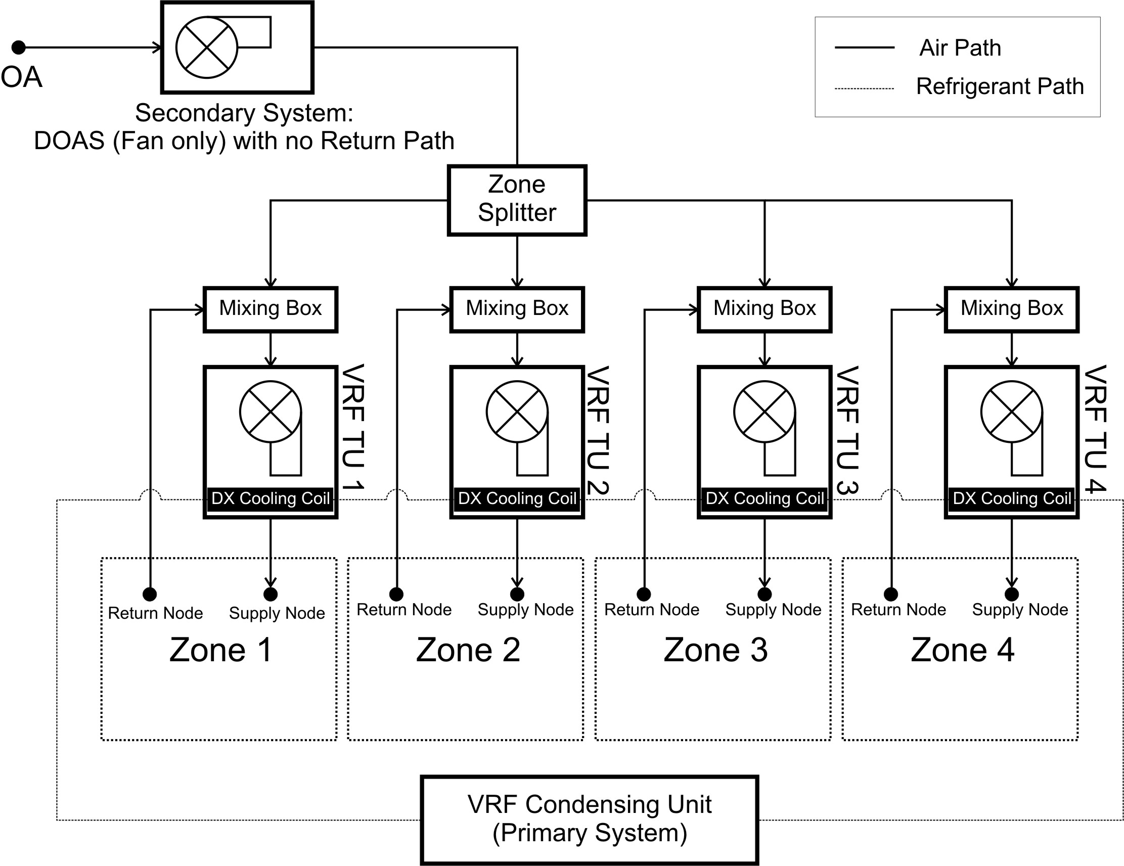
Second question, is it possible to link the supply air from secondary outdoor air system (DOAS) into each primary VRF indoor unit's mixer rather than directly blown into the zone? Presumably by defining ZoneHVAC:EquipmentConnections and tweaking OutdoorAir:Mixer? This attempts always produce severe error messages because DOAS' supply node which was initially serving the zone wont connect into VRF's mixer node.

Any help would be greatly appreciated,

Regards,

edit retag flag offensive close merge delete

2 Answers

Sort by ยป oldest newest most voted
2

answered 2015-12-06 17:13:51 -0500

ad3_pras's avatar

updated 2015-12-06 17:45:40 -0500

diagram.jpg Here I attached the complete diagram of my HVAC system, is there any suggestion how should I model these in EPlus?

edit flag offensive delete link more

Comments

The only thing missing in your configuration, compared to how VRF terminal units are modeled in E+, is the fan heat from the DOAS system. You could use EMS to add some amount of fan heat (0.5C?) to the OA node of each terminal unit. Using EMS, you would set up a sensor and actuator for each terminal unit, then in the EMS program, add the delta T for fan heat to each actuator. EMS is fairly easy to pick up by looking at the example files and documentation. Start with a very simple program to get started.

rraustad's avatar rraustad  ( 2015-12-06 21:38:26 -0500 )edit

Which one do you mean, OA node of VRF TU or ADU TU? For your information, if zone fresh air is served by DOAS, I exclude OA mixer in VRF's TU and directly connects the return air to the TU's cooling coil hence VRF's TU acts like conventional split wall AC which recirculates air inside the zone without any means in providing fresh air from outside. Is it logical? Regards

ad3_pras's avatar ad3_pras  ( 2015-12-08 00:28:30 -0500 )edit

The VRF TU can be connected two ways. Either connect the ADU TU directly to the zone inlet and exhaust node

ZoneHVAC:TerminalUnit:VariableRefrigerantFlow,
 TU1,
 VRFAvailSched,
 TU1 Inlet Node,          !- Terminal Unit Air Inlet Node Name
 TU1 Outlet Node,         !- Terminal Unit Air Outlet Node Name

ZoneHVAC:EquipmentConnections,
 SPACE1-1,
 SPACE1-1 Eq,
 TU1 Outlet Node,
 TU1 Inlet Node,

or you can use an OA mixer and connect the OA mixer inlet node to the zone exhaust node.

Either way, the program checks to see if these connections are made.

rraustad's avatar rraustad  ( 2015-12-08 09:42:57 -0500 )edit

Yes, that is exactly what I did. Except that I combine VRF Supply Inlet and DOAS Supply Inlet within the same Nodelist. Then DOAS Return is connected into Zone Return Air Node and VRF Return is in Zone Exhaust Node. Is it possible to connect VRF Return in Zone Return Air and therefore not using Zone Exhaust Node in attempt to connect DOAS Supply into VRF's OA Mixer? Is there any way to share idf file in this website? I would send you mine if possible. Regards,

ad3_pras's avatar ad3_pras  ( 2015-12-10 19:22:59 -0500 )edit

If you combined the VRF Supply Inlet and DOAS Supply Inlet nodes in the same list, then this means each of these equipment connects directly to the zone through independent zone inlet nodes. ZoneHVAC equipment do not connect to the zone return node.

rraustad's avatar rraustad  ( 2015-12-18 13:13:02 -0500 )edit
2

answered 2015-12-06 10:19:20 -0500

First question: it is possible to use more than 1 VRF terminal unit in a single zone. However, there is no real need to do so unless you are comparing field data to simulation results. Even then the need is minimal since you are ultimately comparing energy use and whether you use 1 or 2 terminal units in the zone should result in nearly the same total energy use. You could partition the zone if you like, and also know that if the system is autosized and the zone is NOT partitioned, each terminal unit will be sized to meet the entire zone load.

Second question: there is not yet a mechanism to connect a DOAS system to the OA inlet of a VRF terminal unit mixer. There are tests while reading the input data that check the zone node connections where the terminal unit's inlet and outlet nodes are connected to the zone exhaust and inlet nodes.

edit flag offensive delete link more

Comments

Thank you for the very quick reply. Indeed, when I checked the sizing report it shows each TU has the same output. At first it worries me because I thought the energy consumed would be doubled too. But in the end its not, since total cooling energy used is actually lower. Please check my answer in this post to get clearer diagram of my HVAC system in my second question.

ad3_pras's avatar ad3_pras  ( 2015-12-06 17:07:24 -0500 )edit

For my second question, with the logic that the used air inside zone is exactly the same as the air which is sucked into the return and later be conditioned inside VRF TU, is it okay for us to assume that the mixing is occurring inside the zone? In fact, location points of DOAS supply in our designed zone are always installed near the VRF's return (either with and without duct). With this logic, could we just model DOAS and VRF conventionally in EnergyPlus?

ad3_pras's avatar ad3_pras  ( 2015-12-07 23:53:04 -0500 )edit

Connecting a DOAS to the inlet of HVAC will change in the inlet conditions entering the coil, and therefore the performance of that coil. It would be better if E+ allowed that connection to better model performance.So for now, using EMS to adjust the inlet conditions to the VRF TU is your only option.The easiest way to do that is to connect the OA mixer and adjust the OA conditions entering the mixer using EMS.

rraustad's avatar rraustad  ( 2015-12-08 09:48:32 -0500 )edit

Could you mention which example files I should look for? In EP v8.4 there are bunch of them. Yet mainly they need sensors, actuators, and programs to give orders. Moreover, I guess there are some keywords in giving orders which should be learned first. Since I'm not proficient in computer language, could you provide an example file which is more specific in adjusting VRF TU's inlet condition by using EMS?

ad3_pras's avatar ad3_pras  ( 2015-12-10 19:10:30 -0500 )edit

All the EMS example files start with EMS. There are not enough example files to show all possible EMS programming techniques. If you run one of the example files, you should find in the edd file something like this:

EnergyManagementSystem:Actuator Available,ZONE1PTHPOAINNODE,Outdoor Air System Node,Drybulb Temperature,[C]
EnergyManagementSystem:Actuator Available,ZONE1PTHPOAINNODE,Outdoor Air System Node,Wetbulb Temperature,[C]

Then set up a sensor for the OA node db and wb temperature. Then use these actuators to set the condition you desire.

rraustad's avatar rraustad  ( 2015-12-18 13:23:39 -0500 )edit

Your Answer

Please start posting anonymously - your entry will be published after you log in or create a new account.

Add Answer

Careers

Question Tools

2 followers

Stats

Asked: 2015-12-06 01:04:46 -0500

Seen: 857 times

Last updated: Dec 06 '15