Question-and-Answer Resource for the Building Energy Modeling Community
Get started with the Help page
Ask Your Question
5

Thermal modeling with complex fenestration systems

asked 2015-09-14 05:42:45 -0500

dayday's avatar

updated 2015-09-14 09:12:21 -0500

Hello everyone,

i am working on complex fenestration systems (CFS) with strong angular dependent transmittance. I wrote a raytracing tool (which i validated) to compute transmittance for various angles.

I later added interfacing to Radiance for daylight computations.

i also added a Perez sky model (diffuse and Direct) to obtain hourly solar gains based on the transmittance. I included a small nodal RC model for a rough estimate of thermal loads in a room.

I would like to validate it against an other tool. it seems like e+ could do the trick. So far i am considering using Construction:ComplexFenestrationState and the 4 matrices (T and R, front and back) and 2 vectors (abs front and back). I am slightly familiar with the XML format used in WINDOW 7 and in Radiance to describe CFSs based on these same matrices. I understand the Basis "LBNLWindow" refers to this representation.

A year ago, when i added the xml representation to my tool for the Radiance part, i did not find a description of this representation and implemented it by studying examples, by trial and error and using the BSDFViewer to "validate" the results. I did it only for the Front transmittance. I need to extend it to Back transmittance and to reflectances. I would like to avoid this uncertain and cumbersome approach. Is there a detailed description available?

I found the relative section in the engineers documentation of Energy plus (pp 170 and on). This helps a little but is still don't know where the patches stop and end...

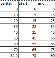
So the main question here is: Where do patches start and end? Given the matrixbasis from the InpoutOutput documentation:

Matrix:TwoDimension, !- matrix for basis definition
CFS_Glz_1_Basis, !- basis matrix name
9, !- number of rows
2, !- number of colums
0.00000, 1.00000,
10.00000, 8.00000,
20.00000, 16.00000,
30.00000, 20.00000,
40.00000, 24.00000,
50.00000, 24.00000,
60.00000, 24.00000,
70.00000, 16.00000,
82.50000, 12.00000;

I would guess:

  • The zenith cone is 20 degrees wide (10° half angle).
  • the next band is from 10 to 20 degrees with the normal.
  • The said band has 8 x 45° patches

  • The first patch in this band is from 0 to 45° azimuth (azimuth origin being defined as in the horizontal plane, on the west side if the normal is south) : p 24 in http://gaia.lbl.gov/btech/papers/3699...

  • ....

  • Last band is from 82.5° to 90° with 12 x 30° patches

Can anyone confirm?

Also, in what unit are these values in the 2d matrix of e+?

Finally, in case any experts are around or people who used this extensively, here are some more questions :)

Are there any other things i should consider using this approach?

How large can the matrix be to get reasonable runtime? (the study focuses on the window, everything around is rather minimalist: single room, adiabatic boundaries....)

Is it possible to have asymmetric matrices? (resolution on the sky side ... (more)

edit retag flag offensive close merge delete

Comments

1

WINDOWS (LBNL) can export to IDF format. Have you checked that? It should help understanding what's what.

Julien Marrec's avatar Julien Marrec  ( 2015-09-14 10:31:35 -0500 )edit

Thanks for the suggestion Julien, that will be very usefull to generate the other layers of the glazing correctly. Maybe i can even import an xml file there...

dayday's avatar dayday  ( 2015-09-15 01:08:58 -0500 )edit

@dayday: sure! I don't know if this does "answer" your question(s) though :)

Julien Marrec's avatar Julien Marrec  ( 2015-09-15 02:23:29 -0500 )edit

1 Answer

Sort by » oldest newest most voted
5

answered 2015-12-01 12:43:36 -0500

vidanovic's avatar

Hi,

let me answer to some of your questions.

Where do patches start and end? Regarding to where patches start and end:

image description

Center angle (we call it theta) is in degrees. Now, for standard basis you would get this (pay attention that first patch is not from 0 to 45 but rather from -22.5 to 22.5 - talking of phi angle here):

image description

I suppose this would answer you question on how pathces are created?

Also, in what unit are these values in the 2d matrix of e+?

As for use in BSDF there are no units except for description of theta angle which is given in degrees.

Are there any other things i should consider using this approach?

Need more details on what exactly are you doing. In general, BSDF should give you pretty much correct results. Pay attention that daylighting model is single-bounce. So no multiple ray bouncing. Everything that goes through BSDF window in EnergyPlus will hit some surface and then will be bounced as perfectly diffuse.

How large can the matrix be to get reasonable runtime?

Go ahead and play with it. We are generally using standard basis (matrix that you exactly described above). However, you are not limited to this. One problem is that WINDOW 7 that is often used to create does not support yet anything that is not standard. It have only: quarter, half and full (standard) basis. Hopefully, that will be changed in near future.

Is it possible to have asymmetric matrices?

No. That is of course possible, but not implemented either in EnergyPlus nor in WINDOW.

Is it possible to treat direct and diffuse separately?

There should be some variables in EnergyPlus that should give you what is coming from diffuse and what is coming from direct beam. Just run it once and take a look at rdd file. That file contains all possible output variables for a given simulation. Once you find desired variable, you still have to insert it into IDF file.

Hope this helps.

Simon

edit flag offensive delete link more

Comments

Hi, may I ask you something regarding your answer in this question: "Everything that goes through BSDF window in EnergyPlus will hit some surface and then will be bounced as perfectly diffuse".

cy's avatar cy  ( 2016-05-11 23:16:57 -0500 )edit

I wonder how Energy Plus handles the lighting redirections through the BSDF data (for thermal calculation), I don't see huge difference when comparing results, but I'd like to know how different is the calculation performed when using the BSDF data [0009] (Matrix Two Dimensions) with the 145x145 data...than when carrying out the calculation using only the Visible and Solar Transmittance and Reflectance data by adding a new glazing system in Open Studio ([0007] Window Material Glazing).. where reflectance data and transmittance are specified at normal incidence. I'd appreciate your reply.Steph

cy's avatar cy  ( 2016-05-11 23:20:23 -0500 )edit

BSDF is used for optical calculations. It will distribute solar and optical properties in a way it is described in BSDF matrix. It will not have huge influence on thermal except that will have little bit different solar distribution inside the room and therefore will have some influence on thermal flow through the window. Note that BSDF will have most of the impact on daylighting calculations and you should get illuminance distribution that is quite different than split-flux method. Speaking of BSDF, the most important improvement should have been seen in windows with shading devices.

vidanovic's avatar vidanovic  ( 2016-05-12 11:12:50 -0500 )edit

I see, there is influence in the solar distribution but not that significant.. thanks a lot!

cy's avatar cy  ( 2016-05-12 15:13:43 -0500 )edit

You should see the biggest difference with shading devices that redirect light. Lets say your shading device redirects light towards the floor and floor is highly absorptive compared to other surfaces. Then you should expect much bigger solar gain compared to standard approach. With specular systems, you will not see big difference. So it is all good.

vidanovic's avatar vidanovic  ( 2016-05-12 15:36:54 -0500 )edit

Your Answer

Please start posting anonymously - your entry will be published after you log in or create a new account.

Add Answer

Careers

Question Tools

3 followers

Stats

Asked: 2015-09-14 05:42:45 -0500

Seen: 602 times

Last updated: Dec 01 '15