This often happens when the original geometry has been imported from other cad tools into SketchUp. The surface matching looks for exact matches in geometry. The intersect tool expects the surfaces to be in the same plane, but if they are offset by even a small amount it may not find an intersection. In the first two images below I moved the south east (relative) cube a fraction of an inch before doing surface matching. As a result it didn't match. There are two approaches for a solution.
- Ideal solution - it would be nice to keep your model clean and get the geometry in the precise position. Then you can re-run surface matching.
- It isn't always easy to fix this geometry, so another alternative is to manually match the surfaces using the OpenStudio inspector. First select one of the two surfaces you want to match, select it and make note of the surface name. Next select to the surface you want to match it to. Once selected go to the "Outside Boundary Condition Object" and then refer to the name of the other surface. This result in the boundary condition of both surfaces being changed to "Surface" and they will refer to each other. If you want to un-match this, then go back to the "Outside Boundary Condition Object" and clear out the surface. Note that you can't manually switch a surface to or from "Surface" boundary condition using the "Outside Boundary Condition" field.
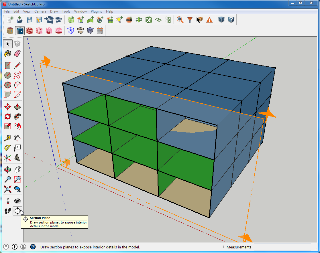 This shows my example problem model. I used a section cut to inspect it for issues while in render by boundary condition. You can select and push the section cut through the building to look at hidden spaces.
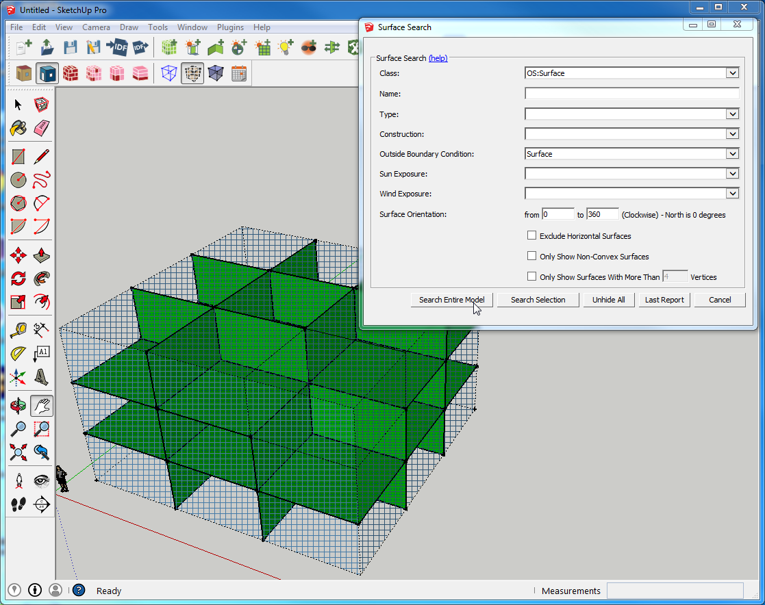 Another nice way to inspect for issues is to use the surface search for surfaces with boundary condition of "Surface" to hide the outside skin of the building. You can also search for "Outdoors" if you only want to see the skin. Add a section cut to this search and it is very powerful.
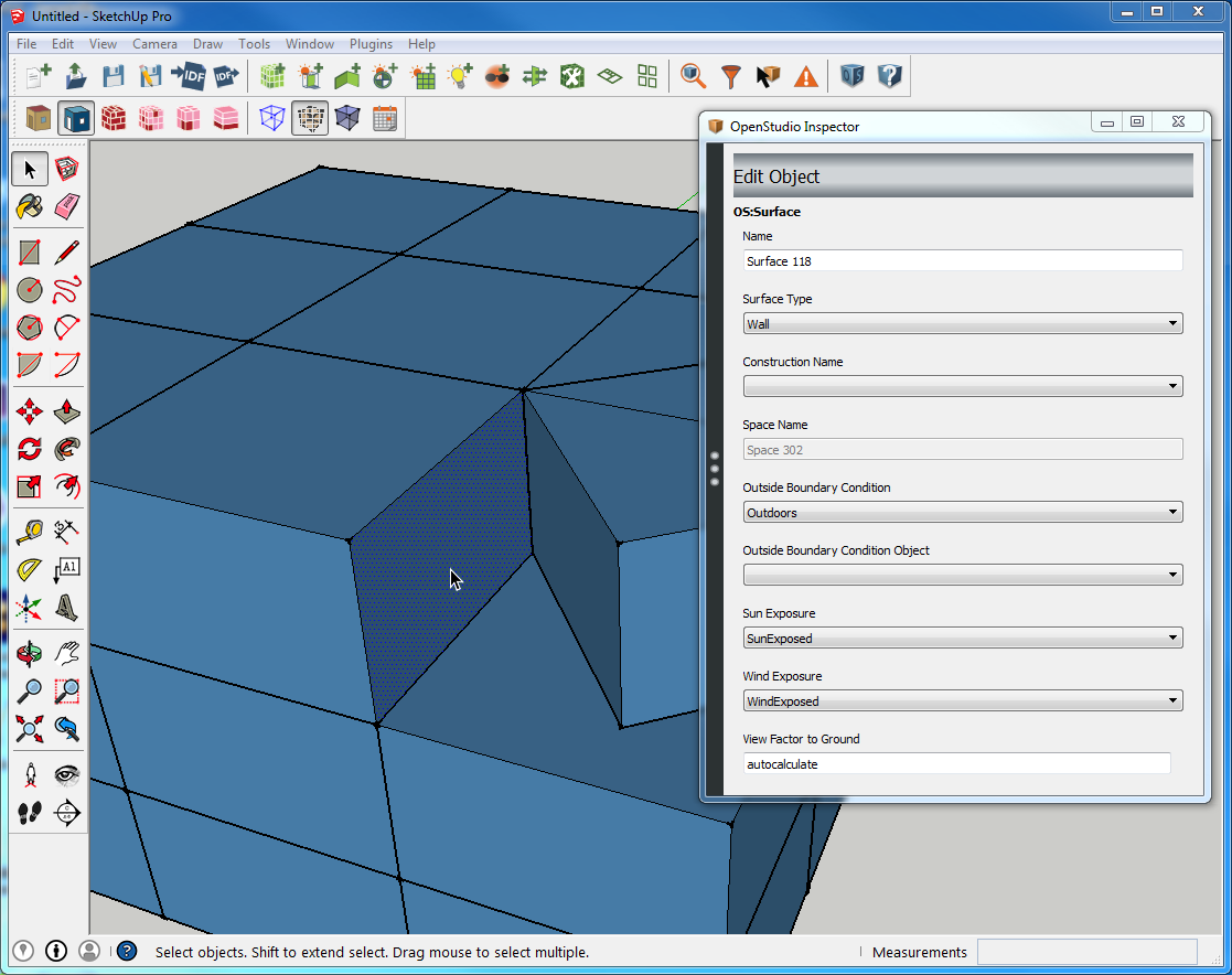 I rotated the problem surface out just for the demonstration, you of course don't want to do this. This is just to show what the the surfaces look like and what the inspector shows to start with.
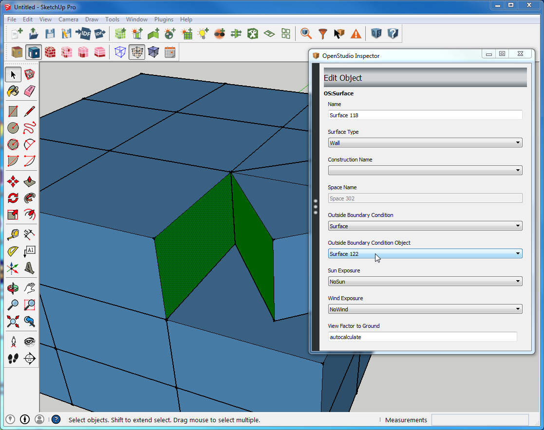 Compare the inspector to the image above. This is how you would force a surface match even if the OpenStudio plugin didn't find it when using the automated tool. A lot of people get caught up trying to manually change the "Outside Boundary Condition" field instead of the "Outside Boundary Condition Object" field. Note: if you are using the legacy plugin you can directly change the "Outside Boundary Condition" field, but you will also have to hand connect the surface pair as well.


