Question-and-Answer Resource for the Building Energy Modeling Community
Get started with the Help page
Ask Your Question
4

VRF with variable fresh air supply

asked 2015-08-20 05:13:55 -0500

Daniel Mak's avatar

updated 2015-11-08 11:10:27 -0500

Dear all,

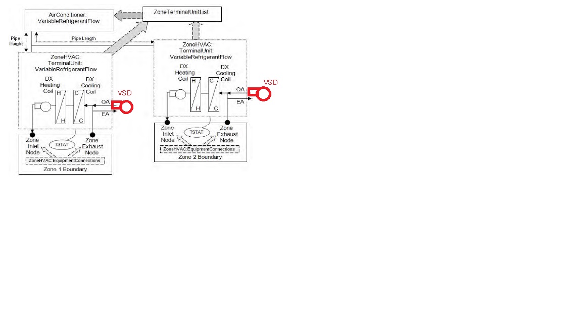
I am trying to model a VRF system with variable flow fresh air fans (in red). As shown in the figure below.

In EnergyPlus (OpenStudio) the is only one fan in each system and it is constant speed (i.e. no red fans). Is there a way I can model the actual design in EnergyPlus or OpenStudio?

Furthermore, when I enter the "Pressure Rise" for the system, should I use the pressure rise for the whole air path, fresh air+internal+exhaust? I believer that might result in an overestimated fan energy consumption because fresh air only makes up a fraction of the supply air. Any advice on that?

Thanks in Advances, Daniel image description

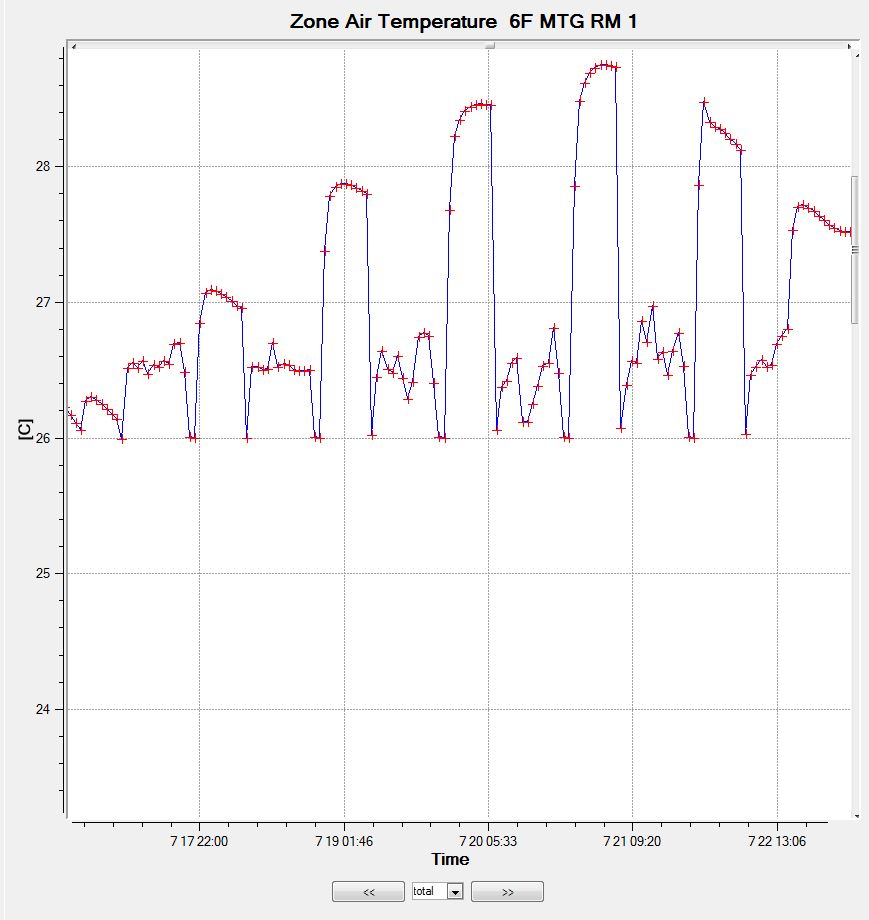
After implementing the ZoneHVAC:OutdoorAirUnit approach the problem is basically solved but the zone temperature is less stable. (Set point = 26C)

This is the zone temperature before image description

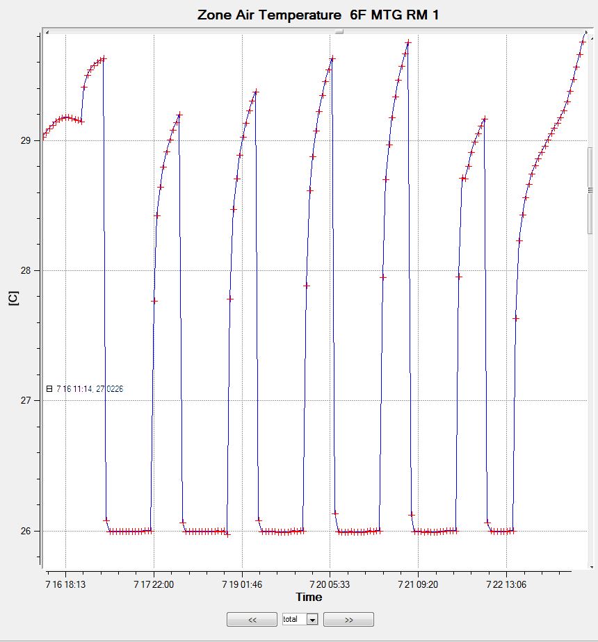
This is the zone temperature after image description

edit retag flag offensive close merge delete

2 Answers

Sort by ยป oldest newest most voted
4

answered 2015-08-20 07:27:39 -0500

updated 2015-08-20 07:29:57 -0500

In EnergyPlus, the zone equipment (ZoneHVAC:*) do not model an outside air system. Instead they model outdoor air mixers integral with the zone equipment model. This means there is only a single fan object and an outdoor air mixer (no OA system as in AirloopHVAC equipment).

ZoneHVAC:TerminalUnit:VariableRefrigerantFlow,
Fan:ConstantVolume,      !- Supply Air Fan Object Type
TU1 VRF Supply Fan,      !- Supply Air Fan Object Name
OutdoorAir:Mixer,        !- Outside Air Mixer Object Type
TU1 OA Mixer,            !- Outside Air Mixer Object Name

Since your terminal unit equipment uses constant fan operation, the amount of outdoor air will not vary while the terminal units are operating. Outdoor air will turn off when the terminal unit turns off (based on availability), but will be constant otherwise.

You could use a cycling fan (Fan:OnOff) to model varying outdoor air proportional to the terminal unit coil PLR, however, this will also vary the terminal unit supply air flow which may not be your intention. To do this, use a 0 in the Supply Air Fan Operating Mode Schedule to denote cycling fan operation, and a 1 to denote constant fan operation. You could use constant fan during occupied hour and cycling fan during unoccupied hours. It's not a bad idea to compare energy use of various cycling fan operation schemes to one that uses constant fan operation mode just so you have an idea of the (fan) energy impacts.

VRFFanSchedule,          !- Supply Air Fan Operating Mode Schedule Name
edit flag offensive delete link more

Comments

1

In other words, for zone HVAC fan systems, EnergyPlus is not capable of implementing a minimum ourdoor air schedule as with DOE2.1e and DOE2.2. EnergyPlus would not meet the requirements of LEED Canada 2009 for modeling CO2 DCV where a minimum outdoor air schedule is to be constructed based on the space occupancy schedule.

Chris Jones's avatar Chris Jones  ( 2015-08-20 09:31:08 -0500 )edit
1

Sorry I didn't mention this before. You could model a VRF system without outdoor air and then use the ZoneHVAC:OutdoorAirUnit object to provide the required amount of OA to the zone. This object has an outdoor air schedule which can be used to vary the OA for occupied and unoccupied periods. When using this method, give the zone OA unit 1st priority and then the terminal unit 2nd priority so it picks up the added OA load.

rraustad's avatar rraustad  ( 2015-08-20 10:26:02 -0500 )edit

Thank you both for the input. I have modelled the system using "OutdoorAirUnit" as suggested and it worked OK. The temperature control was a bit unstable with a +/-1.5C fluctuation around the temperature set point compared with +/-0.5 when using a simple VRF system. I am already quite happy with the result but is there a way to improve the control?

Daniel Mak's avatar Daniel Mak  ( 2015-08-21 03:22:51 -0500 )edit

You would have to describe why the temperature control was unstable.

Is the system switching between cooling and heating? This could be solved by grouping like zones (load wise) on a VRF system.

Is there a problem at the start of occupied hours? This can be solved by starting the HVAC system earlier than occupancy.

rraustad's avatar rraustad  ( 2015-08-21 15:57:48 -0500 )edit

I have uploaded the ESO snap shots of the before-and-after room temperature.

Daniel Mak's avatar Daniel Mak  ( 2015-08-23 22:05:25 -0500 )edit
1

answered 2015-08-20 10:06:58 -0500

nfonner's avatar

updated 2015-08-20 10:16:25 -0500

Caution! Wild assumptions below.

Would it not be possible in OpenStudio to set up an Empty Air Loop without any coils such as an ERV (DOAS) system serving each VRF indoor unit? Obviously, the ERV would not be added to describe the system above. The fan and the AirLoopHVC Outdoor Air System are are the key objects you need. It should not matter, but is the indoor unit supply fan variable speed as well, or is it constant?

There is an attempt to model an ERV (DOAS) in OpenStuio in this forum question: https://unmethours.com/question/8359/....

That post is discussing an ERV (DOAS) providing tempered or even conditioned outdoor air to each VRF indoor unit, which is common practice in my experience. There were errors, according to the original poster, when the loop was modeled without a setpoint manager. I am not sure how you could work around that issue if you are providing raw unconditioned air directly to the indoor unit, unless you ignore the many warnings/ errors associated with a loop setpoint manager without anything to manage. You could always schedule "OFF" the coils you place in order to get the simulation to run, but the warnings will likely be monstrous.

UPDATE: There is a MassFlowRate setting under Setpoint Manager Scheduled - Scheduled Deck Temp for the Control Variable. I am not sure if this fixes the fatal errors that are likely without the manager, but a good place to start.

edit flag offensive delete link more

Comments

I have tried adding an extra air loop in OpenStudio to represent the system but the zone temperatures went completely out of control. I believe that's because I couldn't specify the simulation "priority" in the OpenStudio (at least I don't know where I can set it) so the terminal units were not aware of a separate fresh air supply and fresh air load was not taken care properly by the terminal units.

Daniel Mak's avatar Daniel Mak  ( 2015-08-21 03:29:01 -0500 )edit

I sort of expected to hear this since the approach above models OA direct to the zones instead of upstream of the indoor unit as is the case with Richard's answer above. It appears that there is not a way currently to complete this in the OpenStudio application unless you create a measure.

Do you find this a common system design (without DOAS/ ERV)?

nfonner's avatar nfonner  ( 2015-08-21 11:55:00 -0500 )edit

Your Answer

Please start posting anonymously - your entry will be published after you log in or create a new account.

Add Answer

Careers

Question Tools

4 followers

Stats

Asked: 2015-08-20 05:13:55 -0500

Seen: 1,271 times

Last updated: Aug 23 '15