Question-and-Answer Resource for the Building Energy Modeling Community
Get started with the Help page
Ask Your Question
7

Converting transmittance to transmissivity for IGUs

asked 2014-11-06 15:26:50 -0500

updated 2015-07-10 09:14:21 -0500

Glazing manufacturers and IGU vendors generally provide visible light transmittance of their wares, but Radiance takes transmissivity as input to its "glass" and "trans" materials. The formula typically used for converting transmittance (Tn) to transmissivity (tn) as published in "Rendering with Radiance" (among other places) looks like this:

tn = (sqrt(.8402528435+.0072522239*Tn*Tn)-.9166530661)/.0036261119/Tn

Axel Jacobs also found this simpler factor to work well in most cases:

tn = 1.0895 * Tn (details here, p.21)

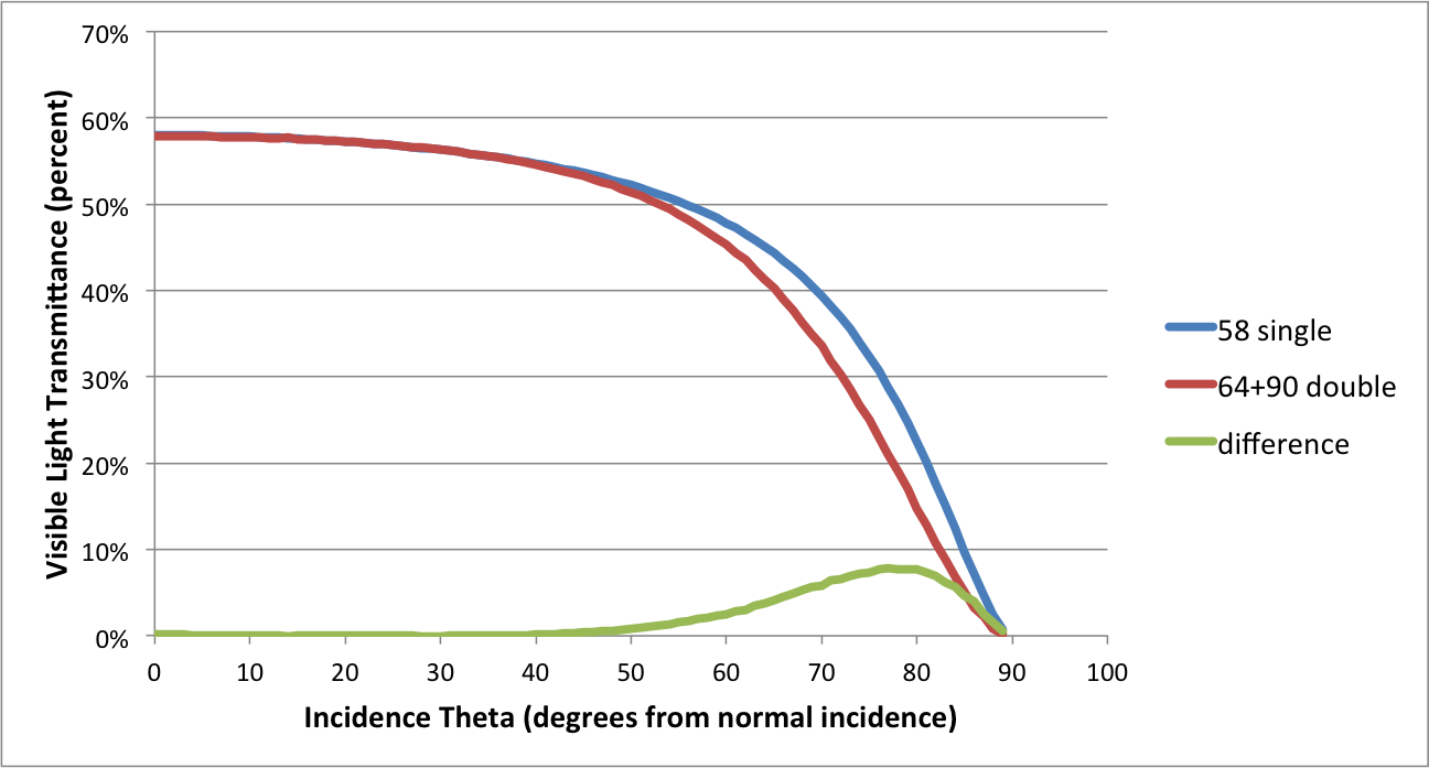
OK so that's great, but transmissivity is the fraction of light not absorbed in one traversal of a single piece of material. And so--at long last--we arrive at the question:

Do these Tn-to-tn conversion formulae fall down when applied to a Tvis number supplied for an inherently multi-paned affair like an IGU? Hmmm?

edit retag flag offensive close merge delete

3 Answers

Sort by » oldest newest most voted
7

answered 2014-11-06 19:46:19 -0500

updated 2014-11-07 15:26:57 -0500

Rob,

You shouldn't use a single glass surface in Radiance to represent a whole IGU, but many do (including myself at times).

The Radiance glass material is an optimization for thin sheets of glass. Fresnel equations are used to determine non-normal transmission. If you model an IGU using a single glass surface with the transmission of the whole IGU your simulation will under predict the fall off in transmission at higher incident angles.

When you have an IGU with two sheets of glass the best option is to either use the glaze script to create a BRTDfunc for your IGU or to use two parallel glass materials. Below is a chart showing the total transmission at different incidence angles for one vs. two glass surfaces to represent an IGU. The chart shows the transmission of an IGU modeled with two glass surfaces (64% transmission and 90% transmission) and one glass surface (58% transmission). The simplification is fine up to 45% off normal, but above 45% the difference becomes more apparent.

image description

Andy


EDIT:
Rob, I just ran a new test (see chart below) including Greg's suggestion and angular transmission results from Window 7. I'm assuming that Window 7 is correct. Greg's suggestion (red line) is further from what Window 7 gives (black Xs) than any of the other options I tested.

here's how the transmissivity was calculated for Greg's suggestion:
IGU Tn= 0.598
IGU Rn= 0.138
tn=0.598/(1-0.138)=0.6937
F=0.101
n=1.936

image description

edit flag offensive delete link more

Comments

You need 10 Karma points to be able to post images. I only have 1 so it might be a while before the chart appears.

Andyrew's avatar Andyrew  ( 2014-11-06 19:47:14 -0500 )edit

You have 11 now.

__AmirRoth__'s avatar __AmirRoth__  ( 2014-11-06 19:50:25 -0500 )edit

Thanks Amir, That happened faster than I expected. I guess karma points aren't that difficult to acquire as I thought.

Andyrew's avatar Andyrew  ( 2014-11-06 19:53:21 -0500 )edit

Andy: I expected the values close to normal incidence to be low, was hoping that the grazing angles would line up better. In retrospect that was just wishful thinking since Greg's alternate method still only took normal incidence values. Oh well. Thanks for doing the due diligence on this!

rpg777's avatar rpg777  ( 2014-11-07 15:32:32 -0500 )edit

So is the BRTDfunc from the glaze script still better (presumably more processor efficient) than the two glass surfaces?

Chris Rush's avatar Chris Rush  ( 2015-08-20 12:37:01 -0500 )edit
2

answered 2014-11-07 11:25:54 -0500

updated 2014-11-07 15:37:34 -0500

Thanks, Andy! Greg Ward also provided the following info, which is worth looking into if you're still interested in representing an IGU as a single polygon (as I am):

The reason the transmittance-to-transmissivity formula looks so complicated is because it takes into account the many internal interreflections that occur to sort out the transmissivity. In this sense, it is not quite the right formula for a multi-paned material, but there is a way to "fake it" if you know the normal reflectance of your system as well as the transmittance.

The file ray/src/cal/cal/trans2.cal contains the following formulae to approximate index of refraction and transmissivity from Rn and Tn:

tn = Tn / (1 - Rn); F = Rn / (1 + tn*tn); n = (1 + sqrt(F)) / (1 - sqrt(F));

"Just use the computed tn and n values for a 'glass' material based on your manufacturer's data, and it should be reasonably close. It would be interesting to compare this approximation to the better one produced by the glaze script or angle-based glazing measurements.

Cheers, -Greg

NOTE: See Andy's latest update to his answer to this post for details on this; it's not the magic bullet.

edit flag offensive delete link more
1

answered 2017-07-25 04:47:22 -0500

ali fatoor's avatar

I know this post is three years old but I wanted to verify the formula used in glass material to calculate the transmittance and transmissivity. I post it here for future reference. Most of this is taken from "Medium and High Temperature" book p.53-54

For homogenous transparent media the light intensity decreases exponentially with layer thickness, as predicted by Beer’s law:

image description

Therefore transmittance, the exited (or transmitted) light intensity over incidence intensity, is:

image description

where s is the thickness of the material and k is extinction coefficient. This quantity applies to a single pass. Hence transmissivity image description 
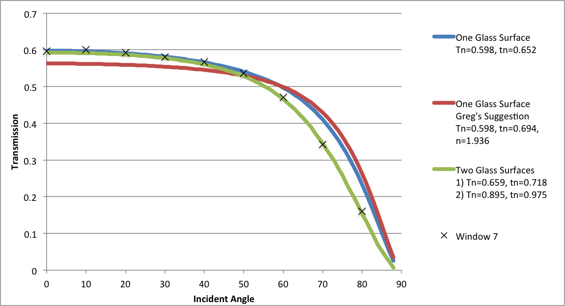
(less used in literature) is a single pass transmittance. In practice a layer of glass will have multiple interreflections which must all be accounted for in calculating the total transmittance τ. The total wavelength-averaged reflectance leaving the top surface divided by the incident flux in below figure can be calculated by summing the infinite series of components making up the total flux.

image description

Using algebra this simplifies to:

image description

Which is what you get in the formula for glass in Behaviour of materials in RADIANCE. These equations were first developed by G. G. Stokes and are called Stokes’ equations.

As mentioned the in the above formula image description applies to a single pass. That’s why it is said that transmissivity excludes multiple interreflction within the medium. Now coming to derivation of transmissivity (which is needed as for glass material parameters calculated using the formula in trans.cal) from normal transmittance τ, we have:

image description

This is in the form of quadratic equation image description. The answers are:

image description

Which is same as what we find in trans.cal file:

sq(x) : xx; rn = sq((1-n)/(1+n)); tn = (sqrt(sq(sq(1-rn))+4sq(rnTn))-sq(1-rn)) / (2sq(rn)*Tn);

The only thing I didn't figured out is why, in Radiance behaviour of materials, the transmissivity later is taken as: image description

edit flag offensive delete link more

Your Answer

Please start posting anonymously - your entry will be published after you log in or create a new account.

Add Answer

Careers

Question Tools

1 follower

Stats

Asked: 2014-11-06 15:26:50 -0500

Seen: 4,153 times

Last updated: Nov 07 '14