EnergyPlus Node Connection Error – “AHU DEMAND INLET NODE” Not Matched to a Controlled Zone


Hi everyone,
I’m having trouble with my EnergyPlus model. I’m receiving the following severe error during the simulation:
** Severe ** An outlet node in AirLoopHVAC="MAIN AIR LOOP" is not connected to any zone
** ~~~ ** Could not match ZoneEquipGroup Inlet Node="AHU DEMAND INLET NODE" to any Supply Air Path or controlled zone
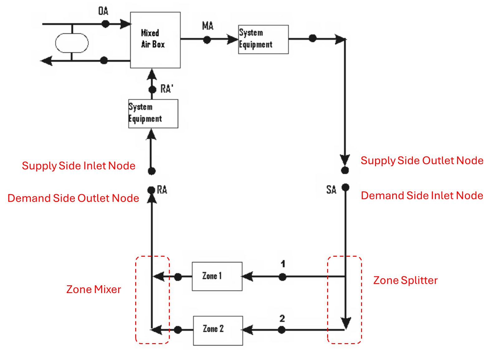
I’ve checked and revised the node names several times. According to the “Edit Node Name” tool in EnergyPlus, AHU DEMAND INLET NODE appears in two places:
In the AirLoopHVAC object under Demand Side Inlet Node Names.
In the AirLoopHVAC:ZoneMixer object under Outlet Node Name.
I understand that this is expected for the return air path. However, EnergyPlus still complains that it can’t match this node to any controlled zone. I suspect that my supply and return air paths might be mixed up somewhere.
Here are the key parts of my code that I believe are relevant:
!- AirLoopHVAC definition
AirLoopHVAC,
  Main Air Loop,           !- Name
  AHU Controller List,     !- Controller List Name
  ,                        !- Availability Manager List Name
  autosize,                !- Design Supply Air Flow Rate {m3/s}
  AHU Branches,            !- Branch List Name
  ,                        !- Connector List Name
  AHU Supply Inlet Node,   !- Supply Side Inlet Node Name
  Zone Return Node,        !- Demand Side Outlet Node Name
  AHU DEMAND INLET NODE,   !- Demand Side Inlet Node Names
  Main Supply Splitter Inlet;  !- Supply Side Outlet Node Names

!- AirLoopHVAC:ZoneSplitter (for supply air)
AirLoopHVAC:ZoneSplitter,
  Main Supply Splitter,           !- Name
  Main Supply Splitter Inlet,     !- Inlet Node Name
  Zone Inlet Node;                !- Outlet 1 Node Name

!- AirLoopHVAC:SupplyPath (routing supply air)
AirLoopHVAC:SupplyPath,
  Main Supply Path,        !- Name
  Main Supply Splitter Inlet,  !- Supply Air Path Inlet Node Name
  AirLoopHVAC:ZoneSplitter, !- Component 1 Object Type
  Main Supply Splitter;    !- Component 1 Name

!- AirLoopHVAC:ZoneMixer (for return air)
AirLoopHVAC:ZoneMixer,
  Main Return Mixer,       !- Name
  AHU DEMAND INLET NODE,   !- Outlet Node Name
  Zone Return Node;        !- Inlet 1 Node Name

!- ZoneHVAC:EquipmentConnections (zone interface)
ZoneHVAC:EquipmentConnections,
  Zone_B_767b7e7f,         !- Zone Name
  Zone Equipment,          !- Zone Conditioning Equipment List Name
  Zone Inlet Node,         !- Zone Air Inlet Node or NodeList Name
  ,                        !- Zone Air Exhaust Node or NodeList Name
  Zone Air Node,           !- Zone Air Node Name
  Zone Return Node;        !- Zone Return Air Node or NodeList Name
Although I have ensured that the supply air path uses Main Supply Splitter Inlet and the controlled zone is connected via Zone Inlet Node (and that AHU DEMAND INLET NODE is reserved for return air via the zone mixer), EnergyPlus still reports that AHU DEMAND INLET NODE isn’t connected to any controlled zone.
Is there a mistake in how I’ve assigned my nodes for supply versus return air?
Could this error be related to another aspect of the system (like the air terminal connections) that I haven’t noticed?
Any insight or suggestions on how to troubleshoot this further would be greatly appreciated!
Thanks in advance for your help.