 | 1 | initial version |
I have done this with other systems and found the best method is through the use of a plant loop with a PlantComponent:TemperatureSource that a pseudo source of fluid. In your case, it would match the GSHP outlet temperatures.
You would set the PlantComponent:TemperatureSource to follow a schedule, which is controlled by a snippet like:
PlantComponent:TemperatureSource,
    GSHP Plant Component Temperature Source,    !- Name of water component in below loop
    Node xxx,                 !- Inlet Node
    Node xxx,                 !- Outlet Node
    Autosize,                 !- Design Volume Flow Rate
    Scheduled,                !- Temperature Specification Type
    8.0,                      !- Source Temperature
    GSHP Water Temperature Schedule;    !- Source Temperature Schedule Name

EXTERNALINTERFACE:FUNCTIONALMOCKUPUNITEXPORT:TO:SCHEDULE,
    GSHP Water Temperature Schedule, !- Match the Schedule Name above
    Any Number,
    <Fluid Temp Variable from GSHP>, !- Variable from Dymola
    0; !- Initial value
You will also want to modulate the Setpoint Manager so that the system operates:
SetpointManager:Scheduled,
    Scheduled GSHP Temp, !- Name of Setpoint Manager in below loop
    Temperature,
    GSHP Water Temperature Schedule, !- Same schedule as above.
    Node xxx;
The pump would be actuated like:
EXTERNALINTERFACE:FUNCTIONALMOCKUPUNITEXPORT:TO:ACTUATOR, !- Use a variable speed pump component
    VarSpdPumpMassFlowActuator, !- This can be any name without spaces
    Var Spd Pump Name, !- This is the name of pump in below loop
    Pump,
    Pump Mass Flow Rate,
    <Fluid mass flow rate from GSHP>, !- This is the name of the variable from Dymola
    0; !- Initial value
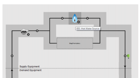
The loop will look something like:

 | 2 | No.2 Revision |
I have done this with other systems and found the best method is through the use of a plant loop with a PlantComponent:TemperatureSource that acts as a pseudo source of fluid. In your case, it would match the GSHP outlet temperatures.
You would set the PlantComponent:TemperatureSource to follow a schedule, which is controlled by a snippet like:
PlantComponent:TemperatureSource,
    GSHP Plant Component Temperature Source,    !- Name of water component in below loop
    Node xxx,                 !- Inlet Node
    Node xxx,                 !- Outlet Node
    Autosize,                 !- Design Volume Flow Rate
    Scheduled,                !- Temperature Specification Type
    8.0,                      !- Source Temperature
    GSHP Water Temperature Schedule;    !- Source Temperature Schedule Name

EXTERNALINTERFACE:FUNCTIONALMOCKUPUNITEXPORT:TO:SCHEDULE,
    GSHP Water Temperature Schedule, !- Match the Schedule Name above
    Any Number,
    <Fluid Temp Variable from GSHP>, !- Variable from Dymola
    0; !- Initial value
You will also want to modulate the Setpoint Manager so that the system operates:
SetpointManager:Scheduled,
    Scheduled GSHP Temp, !- Name of Setpoint Manager in below loop
    Temperature,
    GSHP Water Temperature Schedule, !- Same schedule as above.
    Node xxx;
The pump would be actuated like:
EXTERNALINTERFACE:FUNCTIONALMOCKUPUNITEXPORT:TO:ACTUATOR, !- Use a variable speed pump component
    VarSpdPumpMassFlowActuator, !- This can be any name without spaces
    Var Spd Pump Name, !- This is the name of pump in below loop
    Pump,
    Pump Mass Flow Rate,
    <Fluid mass flow rate from GSHP>, !- This is the name of the variable from Dymola
    0; !- Initial value
The loop will look something like:

