First time here? Check out the Help page!
 | 1 | initial version |
So, I have arrived at the following configuration. The Recharge Loop is supposed to do nothing but pump warmer chilled water from the top of the TES tank and cooler chilled water back to the bottom of the TEES tank, whenever such is deemed necessary. The chiller achieves the necessary cooling, of course. The Discharge Loop is supposed to do nothing but pump cooler chilled water from the bottom of TES tank to the air handler coils and warmer chilled water back to the top of the TES tank.
Recharge Loop: 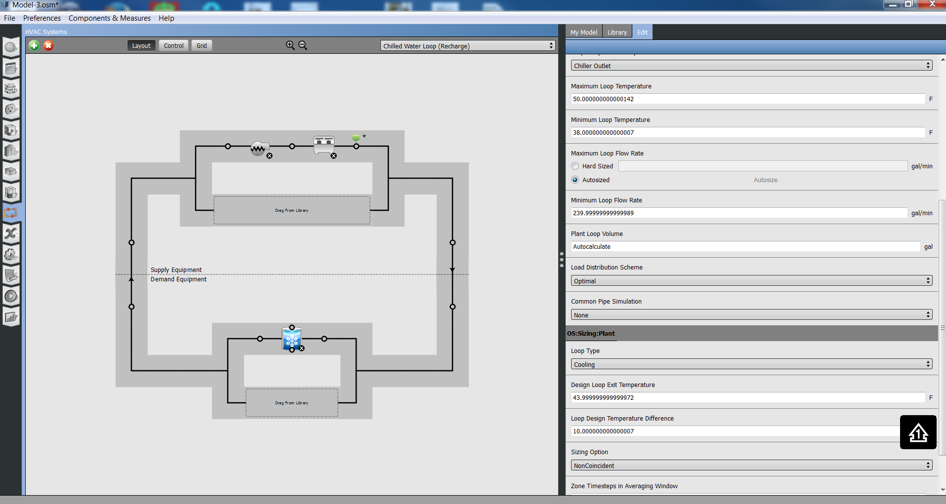
Discharge Loop: 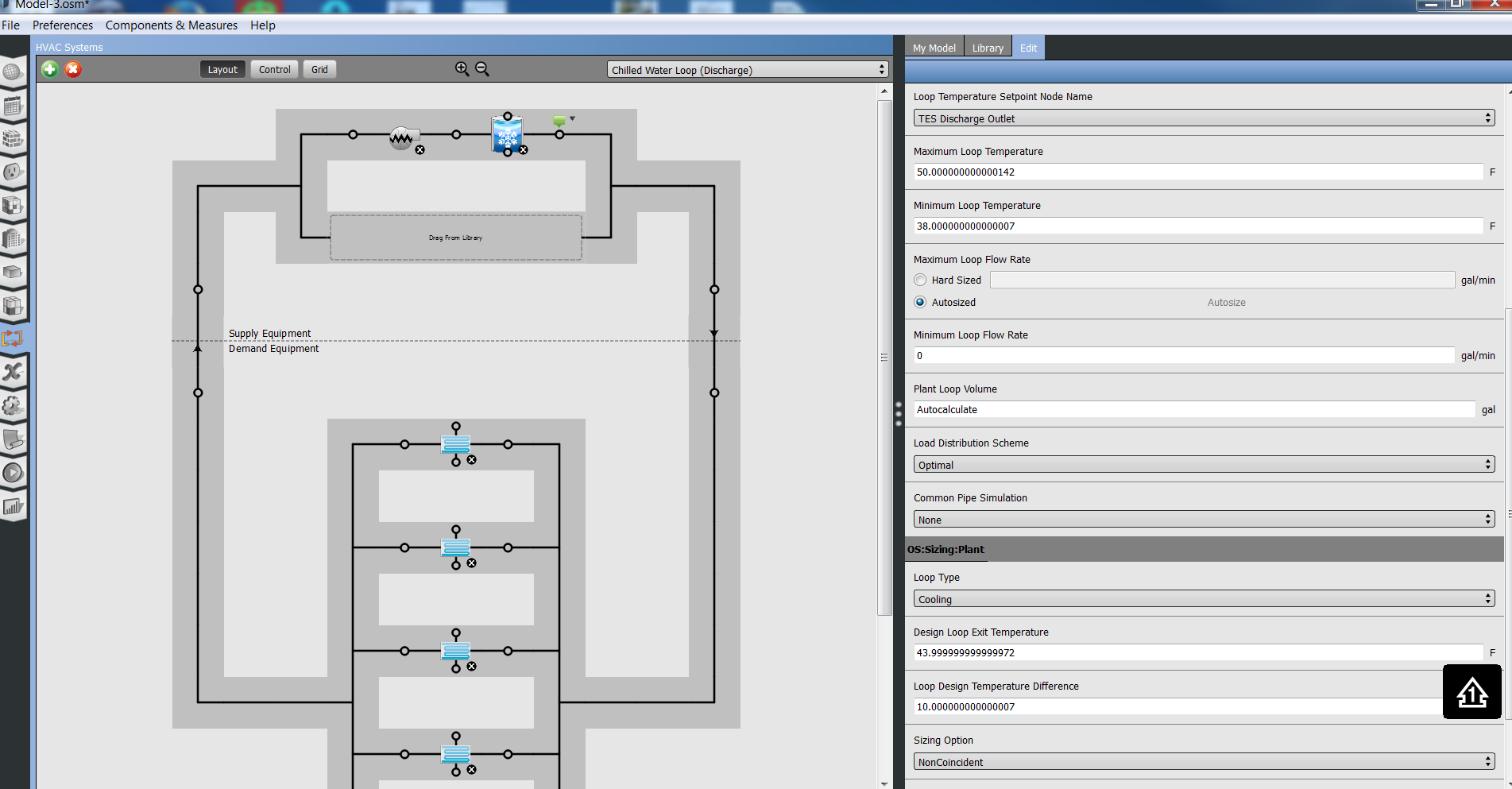
The necessary control is supposed to be achieved through the TES tank dead band temperature. As I understand it, if the temperature at the sensor location (here 10 ft up in a 30 ft TES tank) exceeds the set point temperature (here 44 oF) by the dead band (here 4.5 oF), i.e. reaches 48.5 oF, then the chiller is commanded to come on and chill the TES tank back down via the Recharge Loop.
Speaking of chiller, here are the chiller parameters:
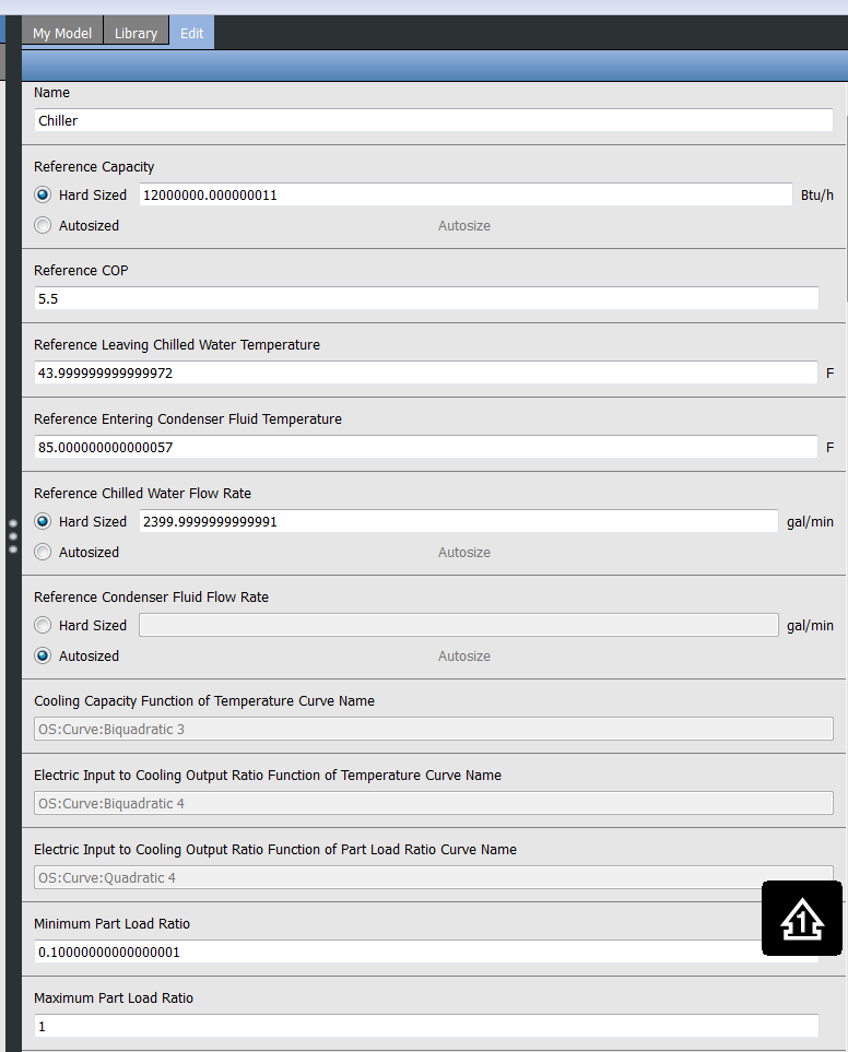
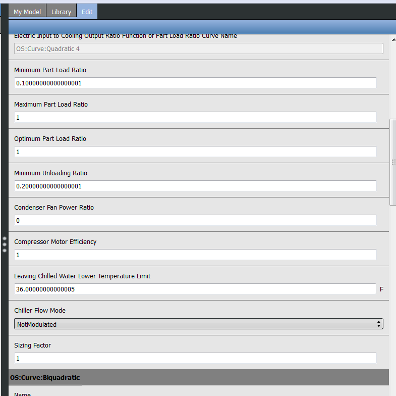
And speaking of TES tank, here are the TES tank parameters:
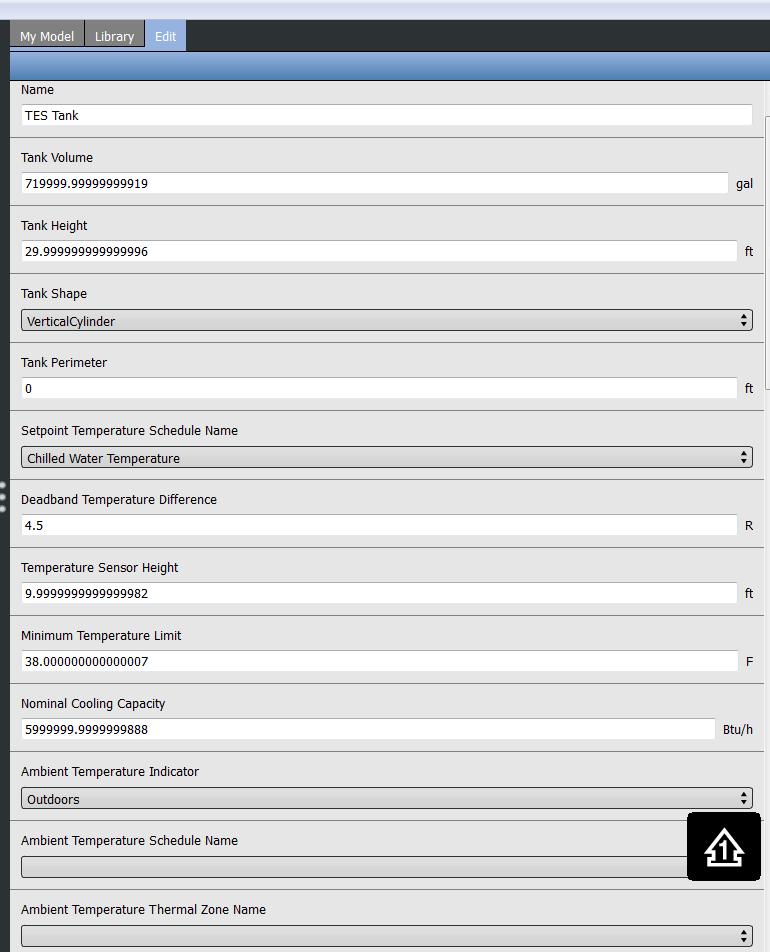
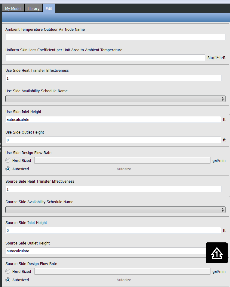
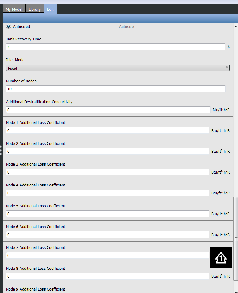
What I observe thus far (by using the OpenStudio Node Diagnostics measure at the two chiller nodes and four TES tank nodes) is not clearly demonstrating to me that this does or does not work. I believe I sized the TES tank and chiller such that the chiller ought to be able to be off for extended periods at a time and just let the TES tank carry the load, yet it seems that the chiller is consuming massive amounts of power most of the day. The two (green) set point managers you see in the above images both reference the CHW set-point schedule (constant 44 oF), by the way.
Not sure if this gets too far into the weeds and is inappropriate for this website, but if not, and if you have any insight here, I would certainly much appreciate such. I believe I am missing something that may be obvious to someone who has been through this before?
Tanks,
Matt Koch
